Biocompatible plastics have revolutionized the medical implant industry, offering distinctive advantages over traditional materials for long-term implantation. These specialized synthetic polymers provide superior performance when used within the human body, ensuring devices don’t trigger adverse reactions. Specifically, PEEK (polyether ether ketone) stands as one of the most common polymer choices for implantable medical devices, available in FDA and USP Class VI approved medical grades.

Since receiving FDA approval in 1998, PEEK has been recognized as a viable polymer for bone substitution. What makes this high-performance thermoplastic particularly valuable is its mechanical properties, which closely resemble those of human bone, providing necessary support and stability in structural implants. Furthermore, PEEK exhibits excellent biocompatibility for long-term implantation while demonstrating remarkable chemical resistance. Although it can be an expensive option, the combination of properties and reliability makes PEEK well worth the investment for medical applications. This guide examines the selection criteria for implant-grade biocompatible plastics, from initial material testing through FDA approval processes, helping engineers and regulatory professionals navigate the complex landscape of medical-grade polymers.


Understanding the Role of Biocompatible Plastics in Implants

Medical device engineers increasingly select polymers over traditional metallic materials for implantable applications. This shift stems from several critical advantages that biocompatible plastics offer in addressing the complex challenges of long-term implantation.

Why Polymers Are Replacing Metals in Medical Devices

The phenomenon of “stress shielding” represents a significant issue with metallic implants. When stainless steel components are implanted, the bone experiences reduced mechanical stimulation due to the implant’s rigidity, eventually leading to loosening over time. In contrast, polymers like PEEK demonstrate flexibility closely matching natural bone structure. This mechanical compatibility reduces interface stress between the implant and surrounding tissue, promoting better long-term integration. Additionally, biocompatible plastics weigh substantially less than metals—up to ten times lighter—while offering superior chemical and corrosion resistance against bodily fluids and sterilization processes.


Examples of Implantable Device Materials in Use Today

The medical implant landscape features several prominent biocompatible polymers. The four traditional mainstay polymers—polyvinyl chloride (PVC), polypropylene (PP), polyethylene (PE), and polystyrene (PS)—continue to serve various applications. However, more specialized materials have emerged for implantable use. PEEK dominates in spinal fusion cages, having largely replaced titanium due to its bone-like mechanical properties. PPSU (polyphenylsulfone) offers exceptional strength, dimensional stability, and compatibility with bodily fluids. Ultra-high molecular weight polyethylene (UHMWPE) serves as a critical component in nearly all total knee replacements and many hip replacements, providing necessary cushioning and movement. Moreover, bioresorbable options like polylactic acid (PLA) and polyglycolic acid (PGA) offer temporary structural support that gradually dissolves as the body heals.


Benefits of Biocompatible Plastics for Long-Term Use

Biocompatible plastics deliver numerous advantages for extended implantation periods. Their inherent resistance to corrosion eliminates degradation concerns that plague metal implants. Furthermore, these materials minimize foreign body reactions—a critical factor in implant longevity. The radiolucency of polymers like PEEK facilitates post-surgical imaging without interference, allowing for more accurate monitoring of healing and potential complications. Notably, the flexibility to modify surface properties through various treatments enhances osseointegration capabilities. Biocompatible polymers also withstand multiple sterilization methods including steam, ethylene oxide, and gamma radiation without compromising structural integrity.


Mechanical and Biological Properties of Common Polymers

The mechanical and biological characteristics of polymers determine their suitability for specific implant applications and their long-term performance within the human body.

Elastic Modulus and Bone-Matching Behavior

The elastic modulus (Young’s modulus) of polymers represents their stiffness or resistance to deformation. This property is crucial for implant selection as bone’s natural modulus ranges from 4 to 30 GPa. Biomaterial engineers seek polymers with comparable values to prevent stress shielding—a phenomenon where overly rigid implants cause bone resorption. Unlike metals with moduli approximately 10 times higher than bone, titanium and its alloys demonstrate values roughly half that of stainless steel, reducing stress shielding risk.

Various factors influence polymer elasticity, including molecular structure, chain flexibility, cross-linking degree, and environmental conditions. Testing methods include ultrasonic pulse velocity measurement, flexural resistance evaluation, and microhardness indentation—with the latter proving effective for estimating elastic moduli of filled polymers.


Wear Resistance and Fatigue Life in Load-Bearing Applications

Implant longevity primarily depends on wear resistance and fatigue life, especially in joint replacements. Primary failure modes include wear, yielding, creep, fatigue, fracture, and delamination. Wear-induced biological failure commonly occurs around hip replacements when debris accumulates, triggering inflammation, bone loss, and aseptic loosening.

Highly crosslinked ultrahigh molecular weight polyethylene (HXLPE) demonstrates superior wear resistance compared to non-crosslinked UHMWPE, consequently reducing particulate debris risk—albeit with diminished toughness and fatigue resistance. Fatigue testing shows biodegraded specimens exhibit 81-95% lower fatigue lifetime compared to non-degraded samples at stress levels between 2.5-10 MPa.


Biocompatibility and Cytotoxicity Profiles

Biocompatibility evaluation follows ISO 10993 standards within a risk management framework. This process begins with assessing material components, manufacturing processes, anatomical location, and exposure duration. The cytotoxicity test, described in ISO 10993-5, serves as the most sensitive initial biocompatibility screening.

Testing typically involves extracting devices in cell culture media and exposing mouse fibroblast (L929) cells to evaluate toxicity. Evaluation methods include qualitative microscopic assessment (grading 0-4) or quantitative measurement using tetrazolium dye to assess cell metabolic activity. Importantly, a failed cytotoxicity test doesn’t necessarily indicate clinical safety risk but requires systematic investigation.


Manufacturing and Post-Processing Considerations

The precision manufacturing of biocompatible plastics presents unique challenges that directly impact implant performance. Properly executed production processes ensure device efficacy while inappropriate methods can compromise biocompatibility and mechanical integrity.


Plastic Machining for Medical Devices: Tolerances and Challenges

Manufacturing biocompatible implants requires exceptional precision. CNC machining can achieve tolerances as tight as ±0.001″ for critical medical components, nevertheless material-specific factors affect achievable precision. Acetal and PEEK components maintain tolerances of +/-.001″, whereas nylon requires more generous allowances at +/-.002″. Furthermore, thermal management presents a significant challenge as polymers have higher coefficients of thermal expansion than metals. Preventing stress-induced warping requires specialized techniques—initially performing rough machining followed by a relaxation period allows internal stresses to dissipate before finishing operations.


Injection Molding vs. Additive Manufacturing for PEEK

Injection molding remains the gold standard for high-volume production of biocompatible implants, offering exceptional dimensional accuracy within tolerances as tight as +/- 0.005 inches. In contrast, additive manufacturing (AM) provides design freedom for complex geometries without sophisticated tooling. Despite these advantages, 3D-printed parts typically demonstrate inferior mechanical properties—approximately 80% lower Young’s modulus and 70% reduced tensile strength compared to injection-molded equivalents. Interestingly, research shows adding 1 wt% IF-WS2 nanoparticles to 3D printed PEEK can overcome reduced stiffness, resulting in properties surpassing unfilled injection-molded PEEK.

Surface Modification for Improved Osseointegration

Surface modification significantly enhances implant integration with bone tissue. Techniques including sand-blasting, large-grit, and acid-etching (SLA) improve mechanical interlocking with adjacent bone. For optimal results, biomimetic approaches create surfaces that mimic natural bone’s micro-nano-scale hierarchical structures. Additionally, coating implants with hydroxyapatite or other calcium phosphates promotes faster osseointegration through improved bioactivity. Surface treatments that incorporate zinc ions demonstrate enhanced antimicrobial properties while stimulating osteoblasts through interaction with Runx2 transcription factors.


Sterilization Effects on Polymer Integrity

Sterilization methods significantly impact polymer performance. High-energy methods (gamma and E-beam irradiation) induce polymer chain scission and crosslinking, altering molecular weight, crystallinity, and mechanical properties. These effects are more pronounced in degradable polymers with polar ester linkages. Steam sterilization (121°C/15min or 134°C/3min) affects surface roughness parameters—reducing maximum height (Sz value) from 41.30μm to 27.49μm in PEEK samples. Consequently, manufacturers must evaluate post-sterilization properties to ensure clinical functionality.

Ready to prototype your next implantable component? Request a quote from AIP’s medical machining team.


Compliance and Approval for Medical-Grade Polymers

Regulatory approval frameworks ensure biocompatible polymers meet stringent safety standards before clinical use. These systems protect patients through comprehensive material evaluation protocols.


ISO 10993 Plastics Testing: Cytotoxicity to Implantation

ISO 10993 serves as the primary standard for biological evaluation of medical devices within a risk management process. The standard requires assessment of physical and chemical characteristics plus exposure parameters including nature, degree, frequency, and duration of bodily contact. Testing typically begins with cytotoxicity (ISO 10993-5), the most sensitive initial biocompatibility screening. For polymers, ISO 10993-13 provides specific guidance on identifying degradation products through accelerated and real-time testing methods.


FDA-Approved Polymers and Device Class Mapping

The FDA categorizes implantable devices primarily as Class II or Class III based on risk factors. Classification considerations include treatment conditions, implantation location, device characteristics, and implantation duration. Class II devices can proceed through 510(k) clearance if risks are identifiable and manageable, whereas Class III devices typically require clinical data through the more rigorous Premarket Approval (PMA) pathway.


Implant Grade Biocompatible Plastics: Certification Process

Implant-grade materials undergo stringent certification requirements to verify biocompatibility, stability, and durability. Documentation must demonstrate non-toxicity, non-carcinogenicity, and non-irritation to biological tissues. USP Class VI represents one certification option, requiring systemic injection, intracutaneous, and implantation tests. Nevertheless, many regulatory authorities consider ISO 10993 more comprehensive, as USP Class VI lacks risk assessment components.


Navigating Custom Device Exemptions and PMA Pathways

The PMA review involves four steps: administrative review, scientific evaluation, advisory committee assessment, and final decision. Alternatively, custom device exemptions exist for unique patient needs, provided devices meet specific criteria including production limits of five units yearly per device type. Such devices must treat sufficiently rare conditions where clinical trials would be impractical.


Conclusion

The selection of biocompatible plastics for implantable medical devices demands careful evaluation of mechanical performance, biological compatibility, and regulatory compliance. Advanced polymers like PEEK, PPSU, and UHMWPE offer advantages over metals through bone-matching elasticity, resistance to stress shielding, and superior chemical durability.

Precision manufacturing—whether through CNC machining or injection molding—directly impacts implant integrity. Surface treatments and sterilization methods must be tailored to each material to maintain structural and biological performance. At the regulatory level, ISO 10993 testing and proper FDA device classification are essential for approval.

For medical engineers and OEMs, choosing the right polymer translates to safer, more effective devices. As polymer technology advances, the focus will remain on enhancing osseointegration, longevity, and patient outcomes.

Ready to prototype your next implantable component? Request a quote from AIP’s medical machining team.


FAQs

Q1. What are the main advantages of using biocompatible plastics in medical implants?

Biocompatible plastics offer several advantages over traditional metals, including reduced stress shielding, lighter weight, superior chemical resistance, and better compatibility with the human body. They also allow for improved imaging and can be modified for enhanced osseointegration.


Q2. How does PEEK compare to other materials for implantable medical devices?

PEEK (polyether ether ketone) is a popular choice for implantable devices due to its mechanical properties that closely resemble human bone. It offers excellent biocompatibility, chemical resistance, and has FDA approval for long-term implantation. While more expensive than some alternatives, its combination of properties makes it valuable for many medical applications.


Q3. What are the key considerations in manufacturing biocompatible plastic implants?

Manufacturing considerations include achieving tight tolerances through CNC machining or injection molding, managing thermal expansion during production, and applying appropriate surface modifications for improved osseointegration. Additionally, the effects of sterilization methods on polymer integrity must be carefully evaluated.


Q4. How are biocompatible plastics tested for safety and regulatory approval?

Biocompatible plastics undergo rigorous testing according to ISO 10993 standards, which include cytotoxicity, sensitization, and implantation tests. The FDA classifies implantable devices based on risk factors, with most falling under Class II or III. Approval processes may involve 510(k) clearance or the more comprehensive Premarket Approval (PMA) pathway.


Q5. What future developments can we expect in biocompatible plastics for medical implants?

Future advancements in biocompatible plastics are likely to focus on improving osseointegration capabilities, enhancing wear resistance, and developing innovative surface treatments. Research may also aim to further refine the mechanical properties of polymers to better match those of human tissues and improve long-term implant performance.

Follow AIP Precision Machining on Linkedin

linkedin logo

ULTEM® aerospace parts play a vital role in the industry because of their exceptional performance characteristics. ULTEM® stands out as one of the few resins with approval for aerospace applications. This 30-year old material powers flight-critical components. Our team at AIP Precision Machining has supplied ULTEM® components to aircraft OEM and MRO providers of all sizes worldwide.

Engineers and procurement specialists need to know the differences between ULTEM® 1000 and ULTEM® 2300 for aerospace applications. ULTEM® 1000, the standard unfilled polyetherimide product, shows impressive strength that goes beyond 1300MPa at room temperature. ULTEM® 2300, with its 30% glass fiber reinforcement, reaches around 2100MPa. The material’s heat distortion temperature sits at 204°C at 264 psi. This makes it perfect for high-temperature aerospace environments. The material stays strong under repeated mechanical stress and meets FAA’s strict flammability regulations.


Key Takeaways

Understanding the critical differences between Ultem® 1000 and 2300 enables aerospace engineers to make informed material selections for mission-critical components based on specific performance requirements.

• Ultem® 1000 excels in electrical applications with superior dielectric strength (830 V/mil) and transparency, making it ideal for avionics housings and electrical insulators.
• Ultem® 2300 provides superior structural performance with 30% glass reinforcement delivering 850,000 psi flexural modulus versus 500,000 psi for Ultem® 1000.
• Thermal expansion differs significantly – Ultem® 2300’s coefficient (1.1 x 10^-5 in/in/°F) matches aluminum, while Ultem® 1000 expands nearly 3x more.
• Machining requirements vary between grades – Ultem® 1000 offers easier machinability, while glass-filled Ultem® 2300 requires specialized tooling and lower speeds.
• Both materials meet stringent aerospace standards including FAA flammability regulations, low outgassing for space applications, and resistance to aviation fluids.

The key decision factor: Choose Ultem® 1000 for electrical insulation and weight-sensitive applications, select Ultem® 2300 for structural components requiring maximum rigidity and dimensional stability under load.


Ultem® 1000 and 2300: Material Overview and Composition

Polyetherimide (PEI), sold under the Ultem® trademark, stands as a breakthrough in high-performance engineering thermoplastics. General Electric introduced this remarkable material in 1982, and it quickly became essential for aerospace applications that need top-notch thermal stability and mechanical strength.

Ultem® 1000: Unfilled PEI for General Aerospace Use

Ultem® 1000 serves as the standard unfilled grade of polyetherimide – you can call it the “virgin” or “neat” resin without additives. This amber-colored, transparent thermoplastic shows impressive mechanical strength that tops 16,500 psi. The material’s excellent hydrolytic stability helps it keep 85% of tensile strength even after 10,000 hours in boiling water. Ultem® 1000 works best where flame resistance, electrical insulation, and chemical stability matter most, making it perfect for interior aircraft parts.


Ultem® 2300: 30% Glass-Filled PEI for High-Rigidity Applications

Ultem® 2300 takes things further by adding 30% glass fiber reinforcement to boost its mechanical properties. This addition lifts tensile strength to about 17,000 psi and flexural modulus to 850,000 psi, which means better dimensional stability than Ultem® 1000. Ultem® 2300’s ability to handle high tensile loads makes it ideal for structural components that face serious mechanical stress in aerospace applications.


Ultem® Polymer Structure and Amorphous Behavior

PEI’s repeating unit has a molecular formula of C₃₇H₂₄O₆N₂ with a molecular weight of 592.61 g/mol. Ultem® differs from semi-crystalline polymers because it’s completely amorphous and contains phthalimide and bisphenol A sub-units. This amorphous structure creates isotropic behavior and reliable dimensional stability across different temperatures. The material’s glass transition temperature reaches 217°C (421°F), which explains its great mechanical properties at high temperatures.


Ultem® Material Properties Relevant to Aerospace

Aerospace engineers value Ultem®’s mix of high strength-to-weight ratio and thermal stability. Both grades deliver outstanding flame resistance with a limiting oxygen index of 47% and meet UL94 V-0 specifications in sections as thin as 0.41 mm. The materials produce very little smoke during combustion, which is crucial for aircraft interior safety. Ultem® also resists aviation fluids well, including jet fuel and hydraulic fluids, and stays strong in these tough operating conditions.


Side-by-Side Performance Metrics for Aerospace Engineers

Aerospace engineers need reliable data to pick the right materials for flight-critical components. Here is a side by side comparison of Ultem® 1000 and 2300:

Performance Category Ultem® 1000 (Unfilled PEI) Ultem® 2300 (30% Glass-Filled PEI)
Tensile Strength 16,500 psi 17,000 psi
Flexural Modulus 500,000 psi 850,000 psi
Thermal Expansion 3.1 × 10⁻⁵ in/in/°F 1.1 × 10⁻⁵ in/in/°F (similar to 6061-T6 aluminum)
Heat Deflection Temp (264 psi) 400°F (204°C) 410°F (210°C)
Dielectric Strength 830 V/mil (higher electrical insulation) 770 V/mil
Surface Resistivity > 10¹³ ohms/square > 10¹³ ohms/square
Weight Considerations Lower density; ideal for lightweight applications Heavier; optimized for strength and rigidity
Machinability Easier to machine; less tool wear More abrasive; requires specialized tooling
Ideal Aerospace Use Cases Avionics housings, electrical insulators, covers Structural brackets, load-bearing components


Tensile Strength and Flexural Modulus Comparison

The tensile strength numbers tell an interesting story. Ultem® 1000 delivers 16,500 psi, and Ultem® 2300 comes in at 17,000 psi. This small difference matters a lot for parts under heavy loads. The flexural modulus shows an even bigger gap – Ultem® 1000 reaches 500,000 psi while Ultem® 2300 hits 850,000 psi. Glass-reinforced Ultem® 2300 proves much better for structural parts that need to resist bending forces.


Thermal Expansion and Heat Deflection Differences

Let’s look at how these materials handle heat. Ultem® 1000’s coefficient of linear thermal expansion is 3.1 x 10^-5 in/in/°F, while Ultem® 2300 comes in at 1.1 x 10^-5 in/in/°F. Ultem® 2300’s thermal expansion matches 6061-T6 aluminum closely, making it perfect for replacing metal parts. The heat deflection temperature at 264 psi shows Ultem® 1000 stays stable up to 400°F (204°C). Ultem® 2300 edges slightly ahead at 410°F (210°C).


Electrical Insulation and Dielectric Strength

Both materials excel at electrical insulation. Ultem® 1000 leads the pack with one of the highest dielectric strengths among thermoplastics at 830 V/mil. Ultem® 2300 follows closely at 770 V/mil. Both materials show surface resistivity above 10^13 ohms/square, which means excellent insulation properties at any frequency.


Weight vs Strength Tradeoffs in Ultem® 1000 Aerospace Parts

Ultem® 2300 might have better mechanical properties, but Ultem® 1000 shines in aerospace applications where weight matters most. Ultem® 1000 matches the strength of filled thermoplastics and adds transparency as a bonus. Its molecular chain flexibility helps absorb impact energy without breaking. This feature proves crucial for parts that might take occasional hits.


CNC Machining Considerations for Ultem® 1000 vs 2300

At AIP Precision, our polymer-exclusive facility specializes in machining Ultem® materials for aerospace applications. Our specialized techniques achieve the highest precision levels. The contamination-free processing we provide will give a solid foundation for flight-critical components.


Chip Formation and Toolpath Optimization

Ultem® creates long, thin chips during machining that might clog cutting tools without proper management. Our team uses tools with high rake angles and optimized chipbreakers to promote quick chip evacuation for Ultem® 1000. High helix end mills work best with Ultem® 2300 because its glass reinforcement produces more abrasive chips that need better management. The team must remove scrap continuously to prevent surface scratches and internal stresses.


Machining-Induced Stress and Warpage

Stress-relieving through annealing helps prepare Ultem® materials before machining. This step reduces surface cracks and internal stresses. Our process for Ultem® 2300 includes post-machining annealing at 300°F to 400°F (150°C to 200°C) for several hours. The material cools slowly afterward. These steps stabilize material dimensions and relieve machining-induced stresses.


Surface Finish Quality in Tight-Tolerance Parts

Tool selection affects surface quality heavily in aerospace components that need precise tolerances. Both grades require sharp carbide tools because of Ultem®’s abrasive nature. Our team switches to a “polishing knife” during the final 0.1mm light cutting process for Ultem® 2300. This approach helps us control surface roughness within Ra < 1.6 μm and meet aerospace industry standards.


Material Removal Rate and Feed Rate Adjustments

Each material needs different cutting parameters. Ultem® 1000 works best at speeds of 800-1200 rpm. Glass-reinforced Ultem® 2300 needs lower speeds of 600-1000 rpm to prevent thermal expansion. Feed rates should stay between 0.05-0.12 mm/rev. Light cuts of 0.3-0.5mm during finishing help maintain geometric accuracy.

AIP brings over 40 years of experience in machining advanced polymers exclusively. We help aerospace teams reduce risk, speed up timelines, and ensure compliance. Our AS9100-certified machining of Ultem® 1000 or Ultem® 2300 delivers high-performance aerospace components with tight tolerances. Contact us today to review your design or request a precision quote.


When to Choose Ultem® 1000 or 2300 for Aerospace Applications

Choosing between Ultem® 1000 and 2300 depends on your aerospace application’s specific needs.


Avionics Housings and Electrical Insulators

Avionics housings and electrical components benefit from Ultem® 1000’s exceptional dielectric strength of 830 V/mil, which makes it the top choice. Ultem® 1000’s volume resistivity is a big deal as it means that it exceeds 10^13 ohms/square, delivering superior electrical insulation across wide frequency ranges. The unfilled Ultem® 1000 stands out when applications need low electrical conductivity and UV radiation resistance. This makes it perfect for sensor housings, electrical connectors, and circuit board components.


Thermal Insulators and Fluid System Components

Ultem® 1000 retains 85% of its tensile strength after 10,000 hours in boiling water, which proves excellent for fluid system components. Notwithstanding that, Ultem® 2300 shows better results in high-temperature fluid systems with its higher heat deflection temperature of 410°F (210°C).

Both materials resist aviation fluids effectively and maintain their structural integrity in fuel systems.


Structural Brackets and Load-Bearing Supports

Ultem® 2300’s 30% glass fiber reinforcement delivers a tensile strength of approximately 2100MPa compared to Ultem® 1000’s 1300MPa. Structural brackets under mechanical stress benefit from Ultem® 2300’s enhanced rigidity. This becomes clear in its flexural modulus of 850,000 psi versus Ultem® 1000’s 500,000 psi. Ultem® 2300 can replace aluminum in structural applications because its thermal expansion coefficient matches 6061-T6 aluminum.


Ultem® Space Applications: Outgassing and Stability

These grades show low outgassing properties, and Ultem® 9085 (a variant) shows remarkably low CVCM values of 0-0.1%. Space applications benefit from Ultem® because outgassing could contaminate sensitive optics or electronics. The material works well in orbital applications due to its dimensional stability under extreme temperature changes.


Precision Plastics Machining for Mission-Critical Parts

Precision-machined components work better with Ultem® 1000 as it causes less tool wear. Ultem® 2300 needs specialized tooling because of its glass fiber abrasiveness.


Conclusion

This piece explores the key differences between Ultem® 1000 and Ultem® 2300 for aerospace applications. These high-performance polymers are a great way to get the right properties for flight-critical components, each with distinct advantages for specific uses.

Ultem® 1000’s unfilled PEI composition delivers superior electrical insulation, making it perfect for avionics housings and components that need excellent dielectric strength. It also offers transparency, impact resistance, and better machinability – clear advantages for many aerospace applications.

The glass fiber reinforcement in Ultem® 2300 makes it excel in structural applications. This boost increases flexural modulus and tensile strength by a lot while bringing thermal expansion down to aluminum-like levels. Aerospace engineers should pick this variant when designing load-bearing brackets and components under mechanical stress.

Both materials showcase remarkable thermal stability, chemical resistance, and flame retardancy – vital properties in aerospace environments. Your specific application needs will determine the choice between these exceptional polymers, whether you need electrical insulation or structural support, lighter weight or maximum rigidity.
AIP Precision’s four decades of experience have taught us these subtle differences through machining these advanced polymers to aerospace specifications. Our polymer-exclusive facility will give a contamination-free processing environment with ±0.002 mm tolerances under AS9100 certification. We use specialized techniques like optimized toolpaths and post-machining annealing to deliver top-quality Ultem® components.

As someone who works closely with aerospace engineers and sourcing managers every day, I’ve seen firsthand how the right material selection impacts long-term performance and program success. Whether you’re deciding between Ultem® 1000 for its electrical insulation or Ultem® 2300 for structural reinforcement, AIP can support your team from concept to final part. If you have questions about which Ultem® grade is right for your aerospace application, feel free to reach out. — Fred Castro, Project Specialist, AIP Precision Machining.


FAQs

Q1. What are the main differences between Ultem® 1000 and Ultem® 2300?
Ultem® 1000 is an unfilled polyetherimide (PEI) with superior electrical properties, while Ultem® 2300 contains 30% glass fiber reinforcement for enhanced mechanical strength. Ultem® 1000 excels in electrical insulation, while Ultem® 2300 is better suited for structural applications requiring high rigidity.


Q2. Which Ultem® grade is better for aerospace structural components?
Ultem® 2300 is generally preferred for aerospace structural components due to its higher flexural modulus (850,000 psi) and tensile strength. Its glass fiber reinforcement provides greater rigidity and dimensional stability under mechanical stress, making it ideal for load-bearing brackets and supports.


Q3. How do Ultem® 1000 and 2300 compare in terms of thermal properties?
Both materials offer excellent thermal stability, but Ultem® 2300 has a slightly higher heat deflection temperature (410°F/210°C) compared to Ultem® 1000 (400°F/204°C). Notably, Ultem® 2300’s thermal expansion coefficient is closer to that of aluminum, making it suitable for metal replacement in certain applications.


Q4. Are there any machining differences between Ultem® 1000 and 2300?
Yes, there are significant machining differences. Ultem® 1000 is generally easier to machine with less tool wear. Ultem® 2300, due to its glass fiber content, requires specialized tooling and lower machining speeds to manage the abrasiveness of the material and maintain surface quality.


Q5. How do these materials perform in terms of flame resistance and chemical stability?
Both Ultem® 1000 and 2300 exhibit excellent flame resistance, meeting UL94 V-0 specifications and FAA flammability regulations. They also demonstrate high chemical stability, maintaining integrity when exposed to aviation fluids, including fuel and hydraulic fluids, making them suitable for various aerospace applications.

Follow AIP Precision Machining on Linkedin

linkedin logo

The aerospace industry now accounts for nearly 16% of the total revenue generated by the additive manufacturing industry. Precision 3D printers have achieved remarkable milestones, exemplified by Relativity Space launching the world’s first 3D-printed rocket in March 2023. Despite these advancements, 3D printing technology still faces significant challenges, including high costs, low printing speeds, limited part sizes, and strength issues.

While different 3D printing technologies offer varying capabilities regarding tolerances—such as MJF at ±0.3% (±0.2 mm), SLS at ±0.3% (±0.3 mm), SLA at ±0.5% (±0.2 mm), and FDM at ±0.5% (±0.5 mm)—they all struggle with fundamental limitations. This variance becomes particularly problematic in highly regulated industries like aerospace and medical device manufacturing, where even slight dimensional inaccuracies can have serious consequences.

Although processes like SLA provide fine finishes and high accuracy, materials undergo shrinkage during curing, creating internal stresses that affect dimensional accuracy. This article examines why even the most advanced 3D printing systems fall short in meeting the stringent requirements of regulated manufacturing environments, and how hybrid manufacturing approaches combining additive and subtractive methods offer a more viable solution.


Dimensional Tolerance Challenges in Precision 3D Printing

Dimensional accuracy remains a significant challenge for manufacturers relying on additive technologies, even with the most sophisticated equipment available. Resolution specifications alone fail to guarantee accurate parts, as multiple factors affect the final dimensional accuracy of printed components.

Inconsistent tolerances in FDM vs SLA vs DMLS

Each 3D printing technology offers notably different tolerance capabilities. FDM systems typically achieve tolerances of ±0.5% (lower limit: ±0.5 mm) for desktop printers and ±0.15% (lower limit: ±0.2 mm) for industrial machines. Furthermore, FDM parts frequently suffer from warping and shrinkage as layers cool at different rates, creating internal stresses that deform prints.

In contrast, SLA technology produces finer tolerances of approximately ±0.2% (lower limit: ±0.1 mm). However, the peeling process during printing can introduce dimensional inaccuracies as pulling forces cause soft prints to bend slightly.

DMLS offers tolerances of ±0.2% (lower limit: ±0.1-0.2 mm), yet the high heat involved in metal sintering often leads to shrinkage issues that must be compensated for in design.


3D printing tolerance for moving parts and assemblies

Achieving functional assemblies with precision 3D printers requires specific clearance considerations. For proper fit between components, manufacturers typically apply clearance gaps of 0.005″ (0.127 mm) for tight fits, 0.010″ (0.254 mm) for normal fits, and 0.020″ (0.508 mm) for loose fits.

Additionally, holes in 3D printed parts consistently print undersized due to limitations of the STL file format, which builds circles from straight-edged triangles. This characteristic necessitates accounting for these deviations when designing critical features.


Impact of anisotropic properties on part accuracy

Layer-by-layer fabrication inherently creates anisotropic characteristics in printed components. Mechanical testing reveals that build orientation significantly influences final properties, with parts built in upright orientation demonstrating especially poor performance.

Research confirms that raster direction substantially affects fracture behavior in FDM parts. For instance, SLA parts printed in 90° orientation exhibit greater strength but increased brittleness compared to other orientations because previously cured layers receive additional laser exposure.

This orientation-dependent performance becomes particularly problematic in regulated industries where consistent mechanical properties are essential across all dimensions. Consequently, the anisotropic nature of 3D printed parts often necessitates subsequent machining operations to achieve the uniform properties and tight tolerances required for aerospace and medical applications.


Material and Surface Limitations in Regulated Applications

Surface finish stands as a fundamental barrier to widespread adoption of additive manufacturing in regulated industries. Surface roughness, a critical quality indicator, directly impacts mechanical, physical, and tribological properties of printed components.


Surface roughness and porosity in aerospace-grade polymers

Internal porosity poses a significant challenge in 3D printed parts, as these invisible voids reduce component density and potentially lead to cracks, leaks, and fatigue. Recent innovations at Oak Ridge National Laboratory have demonstrated that vacuum-assisted extrusion can reduce internal porosity by up to 75% in large-scale polymer prints. This advancement is crucial given that surface irregularities disrupt boundary layer flow and accelerate the transition from laminar to turbulent flow, particularly in aerospace applications such as UAV propellers.

Moreover, surface roughness values vary dramatically between materials and printing technologies. For instance, PLA exhibits higher arithmetic mean roughness values (16.2-17.6 μm) compared to PETG (9.0-10.8 μm) in standard quality prints. These variations significantly influence functional performance, with rougher surfaces leading to enhanced aerodynamic drag and irregular airflow patterns.


Limitations of PEEK additive manufacturing for FDA-compliant parts

PEEK, despite its popularity in medical applications, presents substantial manufacturing challenges. Its high melting temperature, semi-crystalline structure, and significant cooling shrinkage rate increase process complexity and result in uncontrollable properties of 3D-printed parts. Indeed, the crystallization properties of PEEK are greatly affected by thermal history, requiring precise control of printing temperature, ambient temperature, and heat treatment conditions.

Another major obstacle lies in PEEK’s biological inertness, which hinders integration with bone and soft tissue—a critical requirement for medical implants. For dental applications specifically, printing high-resolution small structures (<15 mm) with fine threads proves extremely challenging, primarily because extruding PEEK through small diameter nozzles (<0.2 mm) is difficult due to the polymer’s high melt viscosity.


Post-processing requirements for biocompatible components

Biocompatibility certifications necessitate rigorous post-processing protocols. For instance, to achieve compliance with ISO 10993-5:2009 (cytotoxicity), ISO 10993-10:2021 (sensitization), and ISO 10993-23:2021 (irritation) standards, parts must undergo specific washing and curing processes. Typically, this involves multiple wash cycles in IPA or ethanol, followed by air drying and thermal curing.

File transfer also poses regulatory challenges, as the FDA expresses concerns about consistency across file formats. The ability to verify initial design intent throughout the manufacturing process is essential for traceability and audit purposes. Consequently, post-processing becomes a critical consideration for manufacturers seeking to produce FDA-compliant components.


Why Precision Alone Isn’t Enough for Regulated Manufacturing

Regulated manufacturing environments demand more than just dimensional accuracy from production methods. Precise tolerances serve as merely one aspect of a comprehensive quality system that must satisfy rigorous industry standards.


AS9100 and ISO 13485 compliance requirements

Beyond precise dimensions, AS9100 (aerospace) and ISO 13485 (medical devices) certifications require exhaustive documentation of all manufacturing processes. These standards necessitate controlled procedures, risk management protocols, and regular internal audits. For instance, ISO 13485 mandates complete product identification throughout manufacturing, thorough validation of all processes, and strict control of nonconforming products. Similarly, AS9100 requires detailed first article inspection reports documenting 100% of product characteristics.


Traceability and repeatability in medical device manufacturing

Medical device manufacturing mandates unbroken traceability from raw material to finished product. Every component must be traceable to its manufacturing batch, machine parameters, and operator. Nevertheless, 3D printing creates challenges in this domain as material properties can vary substantially between print jobs due to environmental factors like ambient humidity or temperature fluctuations. These variations undermine the consistency required for validated medical manufacturing processes.


Limitations of 3D printing in achieving validated processes

Process validation, a cornerstone requirement in regulated manufacturing, demands that manufacturers prove their processes consistently produce the same results. Unfortunately, additive manufacturing processes face inherent difficulties achieving this standard. Factors including thermal history, layer adhesion variability, and support structure removal introduce unpredictability that complicates validation efforts. Therefore, while precision 3D printers excel at creating complex geometries, they rarely satisfy the stringent validation requirements of regulated environments without substantial post-processing and secondary operations.


Hybrid Manufacturing: Bridging the Gap with CNC Machining

Hybrid manufacturing is a practical solution that combines the complex geometry capabilities of additive manufacturing with the superior surface finish and tight tolerances of precision machining. This integrated approach effectively addresses the fundamental limitations of standalone 3D printing systems.

Subtractive finishing of 3D printed parts for tight tolerances

Hybrid processes enhance dimensional accuracy dramatically—from Ra30μm in selective laser melting to Ra0.4μm after CNC finishing. Ultimately, this approach enables components to meet the micron-level tolerances required for critical applications. While precision 3D printers typically achieve tolerances around 0.1 mm, CNC machining elevates this to 0.025 mm, making hybrid manufacturing ideal for moving parts and assemblies.


Machined PEEK components for aerospace and medical use

PEEK stands out as an exceptional polymer for regulated applications, offering remarkable properties:

  • Maintains flexural and tensile properties at temperatures exceeding 482°F
  • Withstands over 1,500 steam autoclave cycles without significant degradation
  • Demonstrates exceptional resistance to wear, heat, and radiation

These characteristics make machined PEEK components essential for critical aerospace and medical applications where thermal, chemical, and combustion properties are paramount.


AIP’s polymer-only expertise and certified hybrid workflows

Operating under ISO 13485:2016 compliance with FDA registration status, AIP has achieved tolerance capabilities reaching ±0.002 mm. By exclusively machining plastics, they eliminate metallic cross-contamination risk—vital for biocompatible applications where material purity directly impacts patient safety.

Ready to bridge the gap between additive innovation and certified performance? Partner with AIP Precision Machining to transform your precision 3D printed parts into mission-critical components that meet the highest regulatory and engineering standards. Contact AIP’s engineering team today to discuss hybrid manufacturing solutions built for compliance, consistency, and performance.


Conclusion

Precision 3D printers have advanced rapidly, offering new possibilities in design complexity and rapid prototyping. However, when it comes to regulated manufacturing environments—where compliance, repeatability, and micron-level tolerances are non-negotiable—additive alone isn’t enough.

Across all major 3D printing technologies, issues like dimensional variability, anisotropic mechanical properties, and rough surface finishes continue to challenge part consistency. Materials such as PEEK, ideal for aerospace and medical applications, become difficult to control during additive processing due to shrinkage, crystallization, and thermal instability.

More critically, certifications like AS9100 and ISO 13485 require validated processes, traceability, and consistent outcomes—criteria that additive methods often fail to meet without secondary operations.

This is where hybrid manufacturing provides a decisive advantage. By combining the design freedom of additive with the precision, surface finish, and process control of CNC machining, manufacturers can meet both engineering and regulatory demands.

At AIP Precision Machining, we specialize in this integrated approach. With over 40 years of experience in polymer-only machining, and certified processes for high-performance plastics, we help clients turn printed parts into production-ready, regulation-compliant components.

Follow AIP Precision Machining on Linkedin

linkedin logo

Polyamideimide (PAI) stands as the strongest polymer available today, boasting an exceptional tensile strength of 21,000 psi. When engineers select materials for critical industrial applications, understanding polymer mechanical properties becomes essential for ensuring operational safety and longevity. High-performance polymers like PEEK and Ultem offer impressive tensile strengths of 14,000 psi and 15,200 psi respectively, making them viable alternatives for demanding environments.

The mechanical properties of polymers have gained significant importance as these materials increasingly serve in structural applications, both independently and as matrix materials for composites. Additionally, most polymers exhibit time-dependent mechanical behavior, demonstrated through rate-dependent elastic moduli, yield strength, and post-yield characteristics. This time-dependent nature must be carefully considered when selecting the strongest plastic material for industrial use.

This article examines what truly defines polymer strength in industrial contexts and provides a comprehensive comparison of today’s strongest synthetic polymers. Furthermore, we’ll explore how thermal stability—with materials like PEEK withstanding temperatures up to 260°C and certain polyimide formulations exceeding 300°C—plays a crucial role in material selection for aerospace, automotive, and oil and gas applications.


Defining Strength in Industrial Polymers

Strength in industrial polymers encompasses multiple mechanical properties that determine performance under various loading conditions. Understanding these parameters is essential for selecting materials that can withstand specific industrial demands while maintaining dimensional stability. Engineers must consider several interrelated factors when evaluating polymer strength for critical applications.

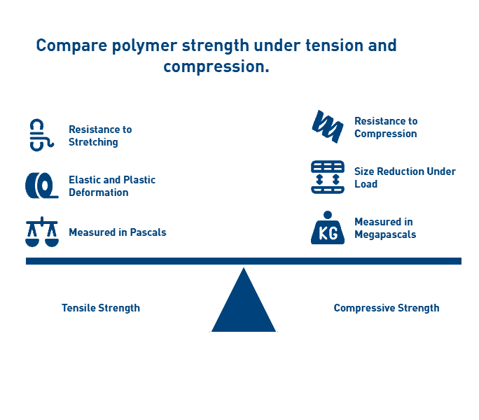
Tensile strength vs compressive strength

Tensile strength measures a polymer’s ability to resist breaking under tension, calculated as the maximum stress a material can withstand while being stretched before failure. In contrast to tensile forces, compressive strength quantifies a material’s capacity to withstand size reduction when subjected to load without fracturing. This fundamental difference exists because tensile stresses separate polymer atoms, while compressive forces bring them closer together.

When subjected to tensile forces, polymers initially undergo elastic deformation where they return to original dimensions upon stress removal. Subsequently, with increased force, they experience plastic deformation—a permanent, irreversible stretching. Tensile strength is typically expressed in Pascals (Pa), Megapascals (MPa), or pounds per square inch (psi).

Compressive strength values often differ significantly from tensile measurements for the same polymer. For instance, polyamide-imide exhibits compressive yield strength of 130 MPa, while polyimide reinforced with glass fiber reaches 220 MPa. These differences highlight why material selection must account for the primary stress type encountered in the application.

The mathematical relationship between stress and cross-sectional area is expressed as: σ = F/A where σ represents stress, F is the applied force, and A is the cross-sectional area. This equation applies to both tensile and compressive scenarios, though the direction of force differs.

Creep resistance and modulus explained

Creep resistance represents a critical property for industrial polymers used in structural applications, especially those subjected to constant loads at elevated temperatures. Creep is defined as the time-dependent deformation that occurs when a solid material is subjected to constant stress below its yield strength. For polymers especially, this phenomenon results from their inherent viscoelastic nature.

The creep process typically progresses through three distinct stages:

  1. Primary creep (Stage I): Characterized by decreasing creep rate as resistance to deformation increases
  2. Secondary creep (Stage II): Exhibits relatively constant creep rate and determines the time to failure
  3. Tertiary creep (Stage III): Shows accelerating deformation due to internal fracturing, leading to failure

Temperature significantly influences creep behavior in polymers. As temperature increases, chain mobility accelerates, resulting in greater creep deformation. One study observed that increasing temperature from 20°C to 50°C caused creep strain to increase 2.15 times, while at 80°C, the increase factor reached 3.93.

Material composition also affects creep resistance. Semi-crystalline polymers generally demonstrate better creep resistance than amorphous polymers because crystalline regions restrict molecular movement. Consequently, polymers with higher crystallinity percentages often exhibit superior dimensional stability under sustained loads.

Young’s modulus (elastic modulus) represents another critical strength parameter, defined as the ratio of stress to strain within a material’s proportional limit. Essentially, it measures a polymer’s stiffness—higher values indicate greater resistance to deformation under load. Modulus values for industrial polymers typically range from 0.7 GPa for HDPE to 12 GPa for glass-fiber reinforced polyimide.

How polymer stress-strain curves are interpreted

Stress-strain curves provide comprehensive insights into polymer mechanical behavior under applied forces. These graphs plot stress (force per unit area) against strain (extension per unit length) as a polymer undergoes deformation. For engineers, these curves reveal crucial information about elastic modulus, yield strength, ultimate tensile strength, and failure characteristics.

A typical polymer stress-strain curve exhibits several distinct regions:

  1. Linear elastic region: The initial straight-line portion where stress and strain are proportional according to Hooke’s Law. The slope of this line defines the Young’s modulus of elasticity.
  2. Yield point: Where the curve deviates from linearity, indicating the transition from elastic to plastic deformation. This represents the stress level at which permanent deformation begins.
  3. Strain hardening region: Beyond the yield point, where plastic deformation continues but requires increasing stress due to molecular realignment.
  4. Ultimate tensile strength: The maximum stress value on the curve, after which necking (localized narrowing) may occur.
  5. Fracture point: Where complete material failure occurs.

Different polymer types produce characteristically different curve shapes. Glassy or semi-crystalline polymers below their glass transition temperature typically show higher modulus values but limited elongation before failure. In contrast, elastomers or semi-crystalline polymers above their glass transition temperature demonstrate lower initial modulus but much greater elongation capacity.

The stress-strain relationship for polymers exhibits significant time and temperature dependence, distinguishing their behavior from other material classes. This viscoelastic nature explains why polymer performance under short-duration testing may not accurately predict long-term behavior under sustained loads—further emphasizing the importance of creep testing for industrial applications.


PEEK: A High-Performance Polymer for Harsh Environments

Polyetheretherketone (PEEK) ranks among the most capable engineering thermoplastics available, defined by its remarkable mechanical stability in extreme environments. Unlike standard polymers, PEEK maintains its structural integrity under conditions that would rapidly degrade conventional materials.

PEEK polymer structure and semi-crystalline behavior

PEEK derives its exceptional properties from its unique molecular architecture—a rigid aromatic backbone composed of repeated units featuring one ketone bond and two ether bonds in an aromatic ring. This chemical structure creates inherent stiffness at the molecular level, contributing to its impressive thermal and mechanical performance.

As a semi-crystalline thermoplastic, PEEK contains both ordered crystalline regions and disordered amorphous zones. The crystalline domains provide strength and chemical resistance, whereas the amorphous regions contribute to toughness and flexibility. Processing conditions significantly influence the final crystallinity level, which can reach up to 48% maximum achievable crystallinity. Higher crystallinity typically results in greater strength and chemical resistance at the expense of some impact resistance.

The semi-crystalline nature gives PEEK excellent wear resistance, dimensional stability, and fatigue resistance—properties that remain largely intact even at elevated temperatures. Moreover, PEEK’s crystalline structure contributes significantly to its exceptional creep resistance, allowing it to withstand sustained loads without permanent deformation.

Tensile strength: 14,000 psi

PEEK exhibits impressive tensile strength of 14,000 psi (90-100 MPa) in its unfilled form, positioning it among the strongest thermoplastic polymers commercially available. This strength level allows PEEK components to replace metal parts in numerous applications while providing substantial weight reduction.

The material demonstrates an elastic modulus of 3.6 GPa, indicating excellent stiffness under load. Indeed, PEEK’s mechanical profile extends beyond mere tensile strength—its flexural strength reaches approximately 25,000 psi (165 MPa), providing exceptional resistance to bending forces.

For applications requiring even greater mechanical performance, carbon fiber-reinforced PEEK grades can achieve tensile strengths of 29,000 psi while maintaining properties at temperatures as high as 299°C. These enhanced formulations offer strength-to-weight ratios that outperform many metals and alloys.

Thermal resistance up to 480ºF

PEEK’s exceptional thermal stability sets it apart from most engineering polymers. The material features a glass transition temperature of approximately 143°C (289°F) and melts around 343°C (649°F). In practical applications, PEEK maintains its mechanical properties at continuous operating temperatures up to 480°F (250°C).

In fact, PEEK can function in steam or high-pressure water environments for thousands of hours at temperatures of 480°F with no significant degradation of properties. This remarkable thermal resilience results from the strong chemical bonds in its aromatic backbone structure.

The material’s thermal durability is complemented by excellent flame resistance. PEEK achieves a UL94 V-0 flammability rating, indicating it resists combustion up to nearly 600°C and produces minimal smoke or toxic emissions when exposed to flame.

Applications in aerospace and oil & gas

In aerospace applications, PEEK’s combination of light weight, high strength, and temperature resistance makes it ideal for replacing metal components. The material finds use in structural brackets, interior components, and applications where weight reduction and flame resistance are critical. As one aerospace industry application highlights, “PEEK polymer has been specified for aircraft landing gear hubcaps withstanding impacts of flying debris and has excellent environmental resistance in harsh conditions”.

Within the oil and gas industry, PEEK excels in extreme downhole environments where temperatures, pressures, and chemical exposure would destroy conventional materials. Applications include:

  • Sealing systems and face seals at wellheads containing high-pressure production fluids and gasses
  • Bearing components that benefit from PEEK’s self-lubricating properties
  • Valve plates, rings, piston rings, and rod packing in reciprocating compressors
  • Labyrinth seals and downhole electrical connectors

PEEK’s combination of properties—including chemical resistance to sour gas environments, excellent wear characteristics, and thermal stability—makes it particularly valuable in these demanding applications. Its ability to maintain structural integrity while resisting corrosion offers significant advantages over traditional metal components in hostile oil field environments.


Torlon (PAI): The Strongest Unfilled Thermoplastic

Torlon (polyamide-imide) stands in a class of its own among engineering thermoplastics, transitioning from thermoplastic to thermoset during post-processing. First and foremost, this unique chemical transformation gives Torlon exceptional mechanical properties that surpass virtually all other melt-processable polymers, making it the material of choice for the most demanding industrial applications.

Tensile strength: 21,000 psi

Torlon PAI boasts the highest tensile strength of any unreinforced thermoplastic at 21,000 psi, establishing it as the strongest polymer available for industrial applications. This exceptional strength results from its molecular structure and the post-curing process that increases molecular weight through chain extension. Alongside impressive tensile properties, Torlon demonstrates remarkable compressive strength exceeding 35,000 psi, far surpassing most engineering plastics.

Notably, Torlon retains its mechanical integrity at extreme temperatures, maintaining functional properties at continuous operating temperatures up to 500°F (260°C). Its heat deflection temperature significantly exceeds that of PEEK, allowing Torlon to retain higher strength and stiffness at elevated temperatures. Despite these high-temperature capabilities, Torlon performs admirably in cryogenic conditions without becoming brittle, offering truly versatile performance across temperature extremes.

The post-curing process dramatically transforms Torlon’s properties, increasing elongation from approximately 5% to 15%. This significant improvement in toughness occurs without sacrificing strength, yielding a material that combines rigidity with impact resistance.

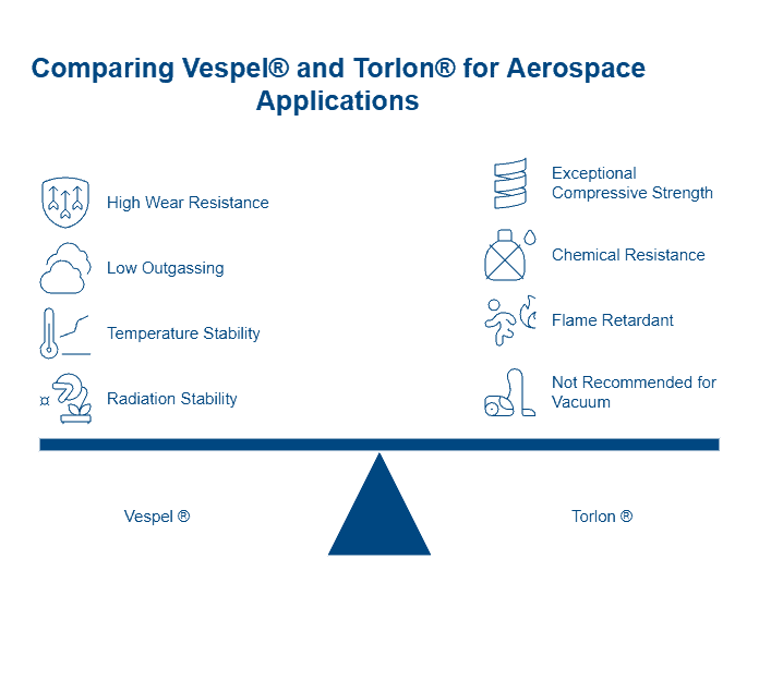
Excellent wear and radiation resistance

Torlon exhibits superior tribological properties that make it exceptionally suitable for wear applications. In particular, wear-resistant grades offer excellent performance under both high velocity and high pressure conditions, often eliminating the need for lubrication. As a result, Torlon excels in applications requiring:

  • Bearings and seal rings in harsh environments
  • Valve seats and piston rings in high-performance engines
  • Precision gears for aerospace applications
  • Compressor components in oil and gas equipment

PAI polymers demonstrate outstanding radiation resistance, significantly outperforming many other engineering plastics when exposed to high levels of radiation. This property proves invaluable for components in nuclear power installations and space applications. Yet another advantage is Torlon’s exceptional chemical resistance to strong acids, most organic compounds, and aviation and automotive fluids, allowing it to function reliably in chemically aggressive environments.

Limitations: brittleness and cost

Nevertheless, Torlon has several limitations that engineers must consider. The material absorbs moisture, which can affect dimensional stability in applications lacking proper humidity control[152]. This moisture absorption becomes particularly concerning for precision components with tight tolerances.

Although post-curing improves toughness, fully cured Torlon cannot be recycled, presenting both economic and environmental challenges. In addition to recycling limitations, Torlon exhibits sensitivity to thermal shock when subjected to sudden high-temperature exposures.

Overall, Torlon typically commands a higher price than other high-performance polymers like PEEK[152]. This cost premium results from its specialized manufacturing processes and unique material properties. Despite the higher investment, many engineers find the cost justified for mission-critical components where performance at temperature extremes and under mechanical stress is essential.

Torlon’s distinctive combination of strength, temperature resistance, and wear properties continues to make it invaluable for applications where other polymers would fail, particularly in aerospace, automotive transmissions, and oil and gas equipment[173] where reliability under extreme conditions is paramount.


Vespel (Polyimide): Superior Creep and Wear Resistance

Vespel stands out among high-performance polymers as a premier polyimide material, renowned for its unmatched combination of thermal stability and mechanical strength in extreme environments. Since its introduction in 1965, this remarkable polymer has established itself as the material of choice for applications where other polymers reach their operational limits.

High-temperature stability beyond 300ºC

Vespel delivers exceptional thermal performance, maintaining structural integrity at temperatures ranging from cryogenic conditions to over 300°C (570°F). For short-term exposure, certain grades can withstand temperatures up to 400°C, with potential to handle up to 538°C (1,000°F) in inert environments. This extraordinary thermal stability stems from Vespel’s unique polyimide molecular structure, which features imide linkages providing dimensional stability even under extreme heat.

Comparatively, Vespel exhibits the lowest coefficient of thermal expansion among unfilled plastics, making it ideal for precision components that must maintain tight tolerances across wide temperature fluctuations. This property, coupled with its outstanding creep characteristics, enables parts machined from Vespel to maintain dimensional stability under sustained loads at elevated temperatures.

Low coefficient of friction in dry environments

Vespel specifically excels in tribological applications, offering self-lubricating properties that eliminate the maintenance requirements typically associated with metal components. Different grades provide varying levels of friction performance:

  • SP-1: The original unfilled grade offering superior wear resistance and insulation properties
  • SP-3: Formulated for vacuum and dry environments with remarkably low outgassing
  • SP-21: Graphite-enhanced grade with improved low-friction properties, functioning effectively with or without lubrication
  • SP-211: Features a lower coefficient of friction than SP-21, incorporating PTFE to further reduce friction even in unlubricated conditions

Vespel’s ductility simultaneously contributes to its excellent sealing capabilities, primarily valuable in valve components where sealing against high-pressure fluids is critical. The polymer’s combination of low friction and exceptional wear resistance results in components that operate reliably for extended periods without lubrication, a significant advantage in environments where lubricants would degrade or contaminate processes.

Ideal for aerospace and semiconductor use

Aerospace engineers have embraced Vespel for its unique performance characteristics in critical applications. The material serves admirably in components such as locking elements for fasteners, valve seats and seals, thermal isolators, bearings, bushings, and splines. Its lightweight construction compared to metals offers substantial weight savings without compromising performance.

In semiconductor manufacturing, Vespel’s high purity and minimal outgassing properties prove invaluable. The SP-3 grade, furthermore, demonstrates superior performance in vacuum environments where contamination must be strictly controlled. The material’s electrical insulation properties coupled with its dimensional stability make it ideal for chip test sockets, wafer clamping rings, and high-temperature substrate handling.

Vespel’s exceptional creep and stress relaxation behavior outperforms virtually all other polymers, enabling it to maintain sealing force in high-pressure applications over extended periods. This characteristic, along with its ability to operate in extreme temperature environments, positions Vespel as an indispensable material for industries where failure is not an option.


Ultem (PEI): Balanced Strength and Machinability

Ultem (polyetherimide or PEI) represents an optimal balance between mechanical performance and processing capability, making it a versatile choice for demanding industrial applications. As an amorphous thermoplastic, Ultem offers a unique combination of properties that position it strategically between standard engineering plastics and ultra-high-performance polymers like PEEK and Torlon.

Tensile strength: 15,200 psi

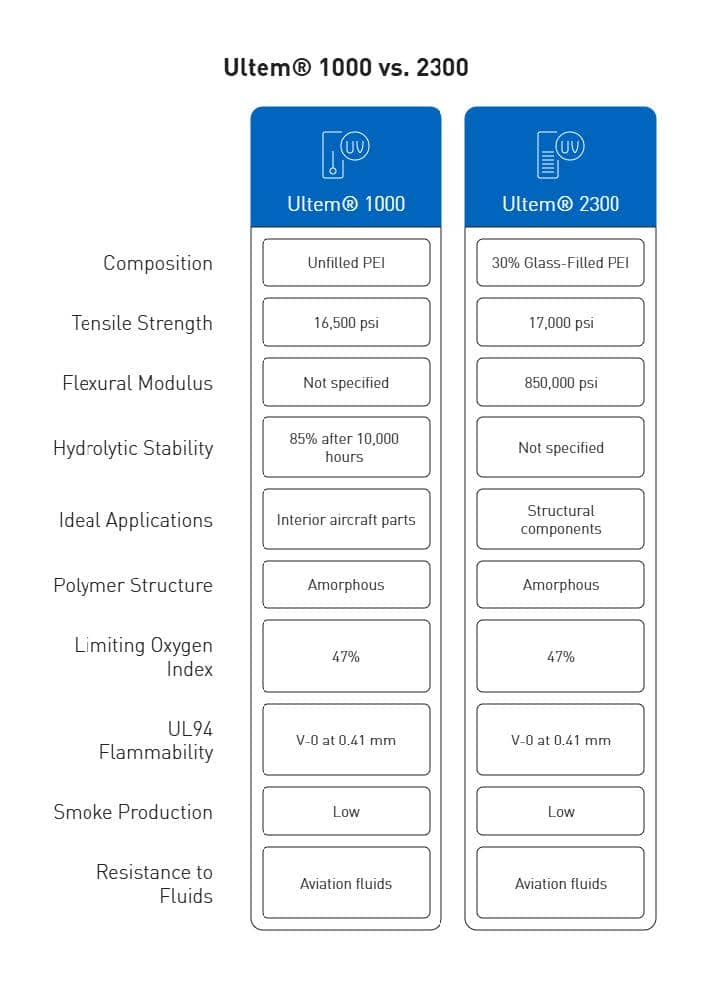
Ultem demonstrates impressive mechanical integrity with a tensile strength of 15,200 psi (105 MPa) in its unfilled grade. This strength level exceeds many standard engineering thermoplastics while providing excellent dimensional stability under load. The material’s mechanical profile extends beyond tensile properties, featuring flexural strength of 20,000 psi and compressive strength reaching 22,000 psi in unfilled grades.

For applications requiring enhanced structural performance, glass-fiber reinforced variants offer substantially improved properties. The Ultem 2000 series includes formulations with various glass fiber contents:

  • Ultem 2100 (10% glass): 16,800 psi tensile strength
  • Ultem 2200 (20% glass): 16,900 psi tensile strength
  • Ultem 2300 (30% glass): 17,000 psi tensile strength

Correspondingly, these reinforced grades exhibit markedly improved flexural strength up to 27,000 psi and compressive strength reaching 32,000 psi. The glass reinforcement primarily enhances rigidity and dimensional stability while maintaining many beneficial characteristics of the base polymer.

High dielectric strength and chemical resistance

Historically, Ultem has been recognized for possessing the highest dielectric strength of any commercially available thermoplastic, measured at 830 V/mil according to ASTM D149. This exceptional electrical insulation capability makes Ultem particularly valuable for circuit boards, high-temperature lighting, electrical connectors, and electronic housings.

Regarding chemical stability, Ultem excels in hot water and steam environments—a distinguishing characteristic among high-performance polymers. The material retains 100% of its tensile strength after 2,000 steam autoclave cycles at 270°F and maintains 85% of tensile strength even after 10,000 hours of immersion in boiling water. Forthwith, this extraordinary hydrolysis resistance makes Ultem suitable for medical devices requiring repeated sterilization and food processing equipment exposed to high-temperature cleaning protocols.

Ultem’s chemical resistance extends to acids, oils, fats, and alcohols, along with exceptional flame resistance without requiring additives. It achieves a UL94 V-0 flammability rating and exhibits a high limiting oxygen index (LOI) of 47%, generating minimal smoke during combustion.

Cost-effective alternative to PEEK

While PEEK offers slightly superior thermal resistance and chemical stability, Ultem provides an economical alternative at approximately one-third the cost. This substantial price difference makes Ultem attractive for applications where PEEK’s extreme properties exceed requirements.

From a processing perspective, Ultem demonstrates excellent machinability compared to PEEK. The material allows for more efficient machining under similar conditions due to its slightly lower strength and reduced tool wear. This processing advantage translates to lower manufacturing costs for precision components while still delivering exceptional performance characteristics.

Ultem’s balanced property profile makes it suitable for diverse applications including aircraft interior components (meeting FAA regulation 25.853 for flammability), medical devices requiring sterilization, automotive electrical systems, and semiconductor manufacturing equipment. For precision machined components requiring tight tolerances, Ultem offers predictable dimensional stability across wide temperature ranges, making it ideal for high-precision industrial parts.


PPS: Chemically Resistant and Thermally Stable

Polyphenylene sulfide (PPS) occupies a strategic position among high-performance polymers, offering an exceptional balance of thermal stability, chemical resistance, and mechanical strength at a moderate price point. With its aromatic rings linked by sulfur atoms, PPS delivers performance capabilities that make it suitable for demanding industrial applications where both chemical exposure and elevated temperatures are concerns.

Tensile strength: 12,500 psi

PPS exhibits impressive tensile strength of 12,500 psi (86 MPa) in its standard formulation, positioning it as the fourth strongest high-performance thermoplastic in unfilled form. For applications requiring enhanced mechanical properties, glass-fiber-reinforced variants achieve tensile strengths up to 17,500 psi, significantly expanding its performance envelope. The material’s compressive strength reaches approximately 21,500 PSI according to ASTM D695 testing, making it suitable for load-bearing components in industrial settings.

Beyond pure strength values, PPS demonstrates excellent rigidity and creep resistance under sustained loads, maintaining its mechanical integrity even at elevated temperatures. This characteristic makes it ideal for precision components that must retain their dimensions under mechanical stress. Among its mechanical attributes, PPS offers:

  • High modulus and exceptional creep resistance
  • Outstanding stress cracking resistance
  • Excellent abrasion resistance and wear properties

These mechanical properties remain largely intact across PPS’s broad operating temperature range, contributing to its reliability in structurally demanding applications.

Excellent dimensional stability and flame retardance

PPS maintains dimensional stability under conditions that would cause significant deformation in conventional polymers. The material exhibits remarkable thermal properties with a melting temperature of 280°C (540°F) and continuous service capability up to 200°C (392°F) with short-term resistance to temperatures as high as 260°C (500°F).

Equally important, PPS demonstrates minimal water absorption below 0.1%, allowing it to maintain dimensional precision across humidity fluctuations—a critical factor for components with tight tolerances. This combination of thermal stability and low moisture absorption results in exceptional dimensional consistency in variable environmental conditions.

Among high-performance polymers, PPS stands out for its inherent flame retardancy. The material achieves UL94 V-0 flammability ratings without requiring additional flame retardant additives. Its molecular structure causes it to merely char during combustion rather than sustain a flame, enhancing safety in applications where fire resistance is critical.

Used in automotive and electrical components

Within the automotive sector, PPS has become invaluable for components exposed to high temperatures, chemicals, and mechanical stress. Primary applications include:

  • Engine components including valve covers and thrust washers
  • Fuel system components owing to resistance to all common automotive fuels
  • Brake system parts requiring thermal stability
  • Under-hood electrical connectors and housings

The electrical and electronics industry similarly benefits from PPS’s unique property profile. Its high dielectric strength coupled with thermal stability makes it ideal for:

  • Electrical connectors and switches requiring reliability in harsh conditions
  • Circuit boards for high-temperature applications
  • Insulators and components for semiconductor manufacturing
  • Electronic housings requiring both flame retardance and dimensional stability

PPS offers manufacturers a valuable alternative to more expensive high-performance polymers like PEEK for applications operating at moderate temperatures. Its exceptional hydrolytic stability—including resistance to hot water, steam, and high-pressure fluids—further expands its utility across diverse industrial settings.


Comparative Analysis of Top 5 Strongest Polymers

When evaluating the top five strongest polymers side by side, critical performance metrics reveal distinct advantages for specific applications. Engineers must carefully weigh these differences when selecting materials for high-stress industrial environments.

Strength-to-weight ratio comparison

The strength-to-weight ratio (specific strength) offers a critical metric for applications where weight reduction provides substantial benefits. Among high-performance polymers, this property varies considerably:

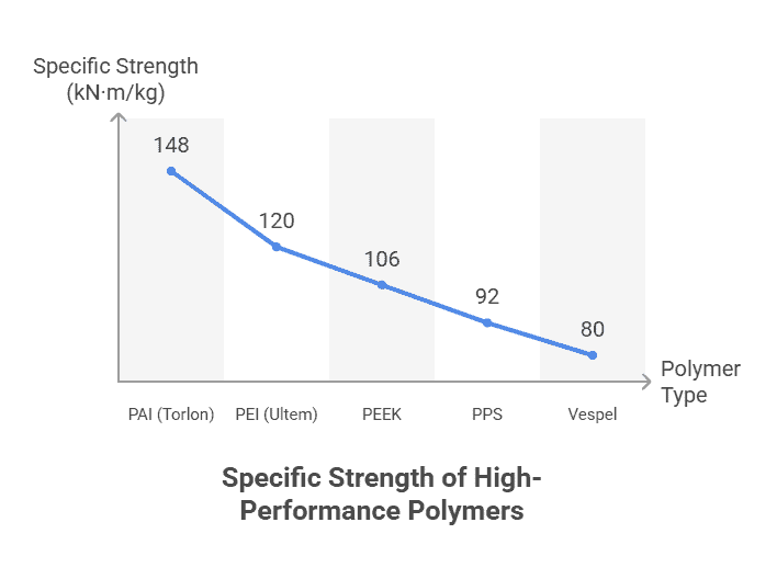
  • PAI (Torlon): With tensile strength of 21,000 psi and density of 1.42 g/cm³, PAI offers the highest specific strength at approximately 148 kN·m/kg
  • PEI (Ultem): Provides 15,200 psi strength with 1.27 g/cm³ density, yielding approximately 120 kN·m/kg
  • PEEK: Delivers 14,000 psi strength with 1.32 g/cm³ density, resulting in approximately 106 kN·m/kg[371]
  • PPS: Exhibits 12,500 psi strength with 1.36 g/cm³ density, providing approximately 92 kN·m/kg
  • Vespel: Despite excellent thermal properties, its specific strength ranks slightly lower among these top five

Primarily, these strength-to-weight ratios exceed those of conventional polymers by factors of 3-5, making them suitable replacements for metal components in weight-critical applications.

Thermal and chemical resistance matrix

Chemical resistance varies substantially across these polymers, with environmental conditions dramatically affecting performance:

PEEK withstands continuous temperatures up to 260°C while maintaining excellent resistance to acids, bases, and hydrocarbons. Alternatively, Vespel operates reliably beyond 300°C—the highest among these materials—yet costs significantly more.

Hydrolytic stability demonstrates another critical difference; Ultem retains 85% of its tensile strength after 10,000 hours in boiling water, outperforming PEEK in this specific measure. Effectively, PPS offers the best overall chemical resistance, particularly against acids and bases, even surpassing PEEK in certain environments.

Maximize Performance with Engineered Polymers – Talk to an AIP expert about selecting and machining the strongest polymer for your demanding environment.

Creep resistance in polymers under load

Creep resistance—the ability to maintain dimensional stability under sustained load—represents a decisive factor for precision components. Temperature substantially impacts this property, with creep strain increasing by factors of 2.15-3.93 as temperatures rise from 20°C to 80°C.

Among these materials, Vespel demonstrates “outstanding creep resistance”, maintaining mechanical properties at continuous temperatures up to 500°F. Likewise, PAI exhibits “superior creep resistance”, making it particularly valuable for tight-tolerance applications.

The molecular structure fundamentally determines creep behavior—polymers with higher crystallinity (like PEEK and PPS) typically outperform amorphous polymers in creep resistance. Higher cross-linking density, typically found in PAI after post-curing, correspondingly enhances long-term dimensional stability under load.


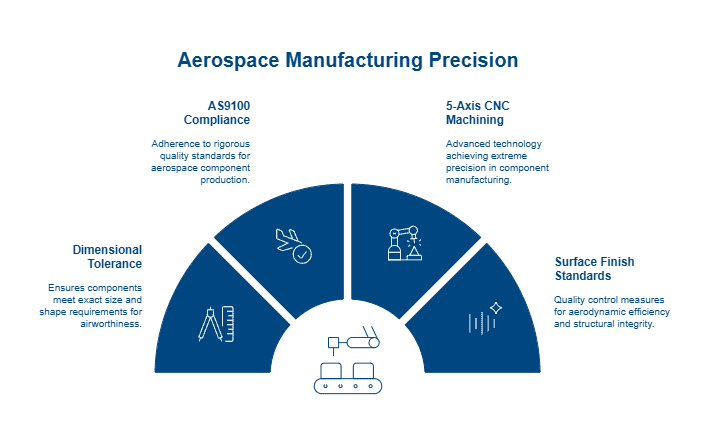
Machinability and Precision Part Considerations

CNC machining delivers precision components for mission-critical applications where high-performance polymers must withstand extreme pressures and stresses. Manufacturing these components involves careful consideration of material properties, machining parameters, and tolerance requirements.

High-pressure plastic components and tolerances

Manufacturing precision plastic parts demands strict adherence to tolerance specifications. Modern aerospace, medical, and defense applications frequently require components with tolerances as precise as ±0.001 inches. Primarily, the material choice significantly impacts achievable tolerances. Materials with low melt points present greater dimensional control challenges.

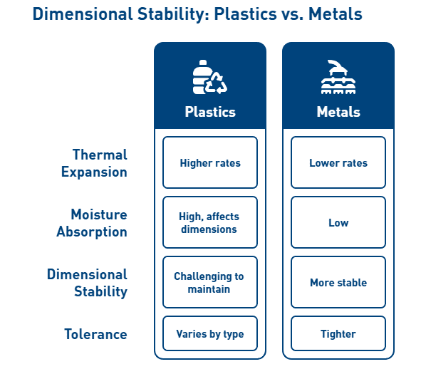
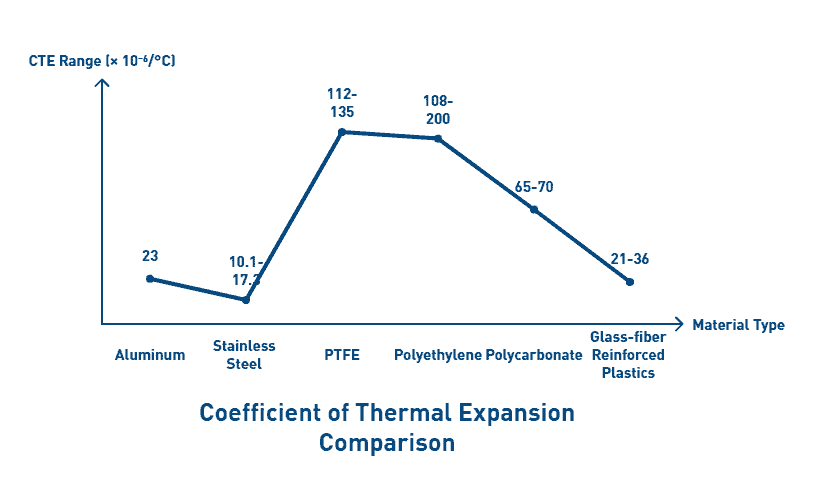
Temperature fluctuations critically affect dimensional stability due to polymer’s high coefficient of thermal expansion (CTE). For instance, UHMW has a CTE of 0.0001 inch/degree, meaning a 10-foot piece can move 0.012 inches with just one degree temperature change. Henceforth, material selection must account for both operational conditions and manufacturing environment.

Machinable polymers for tight tolerances

Among high-performance polymers, achievable tolerances vary considerably:

  • Acetal: ±0.001 inches
  • PEEK: ±0.001 inches
  • Nylon: ±0.002 inches
  • PVC: ±0.002 inches
  • UHMW/HDPE: ±0.005 inches

For optimal machining results, cutting parameters must be carefully controlled. Feed rates typically fall between 0.005 and 0.015 IPR, depending on material and cutting method. To circumvent heat buildup at the cutting interface, manufacturers employ sharp tools, moderate feeds, and high chip evacuation rates.

Fixturing techniques prove equally important. Since polymers are more elastic than metals, they become susceptible to deformation under excessive clamping pressure. In this case, customized fixtures providing support without excessive force yield better results.

How AIP Precision Machining supports material selection

With over 37 years of experience working with professionals across medical sciences, aerospace, defense, and specialized industrial sectors, AIP assists clients in navigating crucial material selection factors including:

  • Electrical properties and dielectric requirements
  • Mechanical strength and wear resistance
  • Chemical exposure considerations
  • Thermal stability requirements
  • Industry-specific standards and regulations

In order to deliver optimal machined products, AIP employs state-of-the-art technology and maintains high quality standards throughout the manufacturing process, consistently achieving tight tolerances of ±0.001 inches or better.


Conclusion: Strategic Selection of High-Performance Polymers

Selecting the optimal polymer for demanding industrial applications requires thorough analysis of multiple performance factors beyond simple strength measurements. Throughout this examination of high-performance polymers, PAI (Torlon) clearly emerges as the strongest available option with its remarkable 21,000 psi tensile strength. Nevertheless, material selection decisions must consider application-specific requirements rather than relying solely on strength values.

Each polymer discussed offers distinct advantages for particular environments. PEEK delivers exceptional chemical resistance and thermal stability up to 260°C, making it suitable for harsh chemical settings. Vespel stands out with superior creep resistance and thermal performance beyond 300°C, though at higher cost. Ultem provides an economical alternative with balanced properties and excellent dielectric strength. PPS offers outstanding chemical resistance with inherent flame retardancy at a moderate price point.

Engineers must consequently evaluate several critical factors when selecting materials:

  • Mechanical requirements (tensile strength, compressive strength, modulus)
  • Thermal stability needs (maximum continuous operating temperature)
  • Chemical exposure conditions
  • Creep resistance under sustained loads
  • Dimensional stability requirements
  • Cost constraints

Undoubtedly, the strength-to-weight ratio becomes particularly significant when weight reduction provides substantial benefits. PAI offers the highest specific strength at approximately 148 kN·m/kg, followed by PEI at 120 kN·m/kg and PEEK at 106 kN·m/kg. These values exceed conventional polymers by factors of 3-5, making them viable replacements for metal components in weight-critical applications.

Temperature significantly influences polymer performance, especially regarding creep behavior. As temperatures rise from 20°C to 80°C, creep strain increases dramatically, underscoring the importance of evaluating materials under actual operating conditions rather than relying solely on room-temperature data.

The manufacturing process additionally plays a crucial role in component performance. Precision machining capabilities must match the selected material’s properties to achieve required tolerances. Materials with higher dimensional stability generally allow for tighter tolerances during manufacturing.

Most importantly, engineers should approach polymer selection as a multi-dimensional decision process, considering the complete performance profile rather than focusing exclusively on strength values. This comprehensive approach ensures optimal material selection for critical industrial applications where failure is not an option.

For engineers tasked with selecting the strongest polymer for high-pressure, high-stress environments, working with a precision machining partner is essential. AIP Precision Machining brings over 40 years of specialized experience in high-performance thermoplastics, providing expert guidance in material selection and delivering components that meet the most demanding tolerance and performance requirements. Contact AIP today to discuss your application needs and ensure optimal performance through expertly machined polymer solutions.


FAQs

Q1. What is the strongest polymer available for industrial applications?

Polyamide-imide (PAI), also known as Torlon, is currently the strongest polymer available for industrial use. It has an exceptional tensile strength of 21,000 psi, making it ideal for demanding applications where high strength is critical.

Q2. How does PEEK compare to other high-performance polymers?

PEEK offers an excellent balance of properties, including high tensile strength (14,000 psi), thermal stability up to 480°F, and chemical resistance. While not as strong as PAI, PEEK outperforms many other polymers and is widely used in aerospace and oil & gas industries.

Q3. What are the key factors to consider when selecting a polymer for industrial use?

When selecting a polymer, consider mechanical properties (strength, stiffness), thermal stability, chemical resistance, creep behavior, dimensional stability, and cost. The specific requirements of your application should guide the selection process.

Q4. Which polymer offers the best combination of strength and cost-effectiveness?

Ultem (PEI) offers a good balance of strength (15,200 psi tensile strength) and cost-effectiveness. It’s often considered a more economical alternative to PEEK for applications that don’t require extreme temperature or chemical resistance.

Q5. How do high-performance polymers compare to metals in terms of strength-to-weight ratio?

High-performance polymers like PAI, PEI, and PEEK offer strength-to-weight ratios that exceed conventional materials by 3-5 times. This makes them excellent alternatives to metals in weight-critical applications, particularly in aerospace and automotive industries.

Follow AIP Precision Machining on Linkedin

linkedin logo

In aerospace engineering, the search for materials that can meet stringent performance criteria like being light weight, having thermal resistance, and providing electromagnetic interference (EMI) shielding is relentless. Historically, metals were the go-to choice, but their limitations in weight and corrosion resistance posed significant challenges. Enter Magnetic Polymer Nanocomposites In Aerospace – a game-changer in material science.

Polymer nanocomposites, particularly magnetic polymer nanocomposites (MPNs), have emerged as the leading option in addressing these challenges. Their unique composition – a polymeric matrix reinforced with nanometric-sized fillers – gives them a blend of properties from both polymers and magnetic materials. This synergy is crucial for aerospace applications where every ounce matters, and every degree of thermal resistance can be the difference between success and failure.


Section Key Takeaways
MPNs Composition and Characteristics Description of MPNs, their polymeric matrix, and magnetic nanoparticles. Importance in reducing aircraft weight and enhancing performance.
Synthesis Methods Various methods like molding, coprecipitation, and in situ precipitation used to fabricate MPNs. Each method’s advantages and unique features.
Characterization Techniques Importance of characterizing MPNs using techniques like Computational Modeling, AFM, TEM, and Raman Spectroscopy.
Aerospace Applications Applications of MPNs in EMI Shielding, Coatings and Paints, and Structural Health Monitoring. Their role in enhancing safety and efficiency.
Future Research Trends Focus on eco-friendly approaches, industrial scalability, and enhanced functionalities in MPNs.


Magnetic Polymer Nanocomposites: Composition and Characteristics

Magnetic Polymer Nanocomposites (MPNs) are formed by embedding magnetic particles, typically in the nanoscale range, into a polymer matrix. The matrix material, often a lightweight polymer, provides structural integrity, while the magnetic nanoparticles impart unique magnetic properties.

The matrix can vary widely, from common thermoplastics to high-performance polymers, each selected based on the desired balance of mechanical, thermal, and magnetic characteristics. The choice of magnetic particles, like iron oxide or nickel, is equally critical. These nanoparticles grant the MPNs their distinctive magnetic behavior, essential for applications like electromagnetic interference (EMI) shielding and sensor technology.

In aerospace, the impact of MPNs is profound. They contribute to reducing the overall weight of aircraft, a paramount goal in aerospace engineering. Lighter aircraft are more fuel-efficient, leading to cost savings and reduced environmental impact. Additionally, their enhanced performance characteristics, like thermal stability and corrosion resistance, make them ideal for the harsh conditions encountered in aerospace environments.


Synthesis of Magnetic Polymer Nanocomposites

The fabrication of MPNs is a sophisticated process, crucial to achieving the desired properties. Common methods include:


  1. Molding: This involves embedding magnetic nanoparticles into the polymer matrix during the molding process. It’s a direct and efficient method, suitable for large-scale production.
  2. Copolymerization and In Situ Precipitation: These techniques involve forming the polymer matrix around the magnetic particles. This results in a more uniform distribution of nanoparticles, enhancing the magnetic properties.
  3. Blending and Grafting: These are used to modify existing polymers, adding magnetic nanoparticles to the mix. The key here is achieving a homogeneous mixture to ensure consistent properties throughout the material.


Each method has its own set of advantages, ranging from ease of production to the degree of control over the final properties. The choice of method is dictated by the specific application requirements in the aerospace industry.


Characterization of Polymer Nanocomposites for Aerospace

Characterization is pivotal in understanding and refining the properties of MPNs. It involves a range of techniques:

  1. Computational Modeling: Used for predicting the behavior of nanocomposites under various conditions.
  2. Atomic Force Microscopy (AFM) and Transmission Electron Microscopy (TEM): These provide insights into the nanoscale structure of the composites.
  3. Raman Spectroscopy and X-ray Diffraction: Essential for understanding the chemical composition and crystalline structure.
  4. Thermal Characterization: Determines how the material behaves under different temperature conditions, critical for aerospace applications.


Characterization sets the stage for practical application. The real test of magnetic polymer nanocomposites lies in their performance in real-world aerospace applications. From shielding sensitive equipment to enhancing structural integrity, MPNs are making significant strides in aerospace technology.


Aerospace Applications of Magnetic Polymer Nanocomposites

In the aerospace industry, the applications of magnetic polymer nanocomposites (MPNs) are as varied as they are critical. These materials are increasingly employed in areas where traditional materials may fall short. Key applications include:

  1. Electromagnetic Interference (EMI) Shielding: MPNs are ideal for EMI shielding due to their magnetic properties. In aerospace, where electronic systems must operate without interference, these materials protect sensitive equipment from external electromagnetic fields.
  2. Coatings and Paints: MPNs are used in specialized coatings and paints for aerospace vehicles. These coatings provide not just aesthetic enhancements but also functional benefits like corrosion resistance, thermal stability, and improved aerodynamics.
  3. Structural Health Monitoring (SHM): With their inherent magnetic properties, MPNs are used in sensors embedded within aerospace structures for real-time monitoring. These sensors can detect stress, strain, and even micro-damage, enabling proactive maintenance and ensuring the integrity of the aircraft.


These applications demonstrate the versatility and indispensability of MPNs in modern aerospace design and maintenance. They offer a blend of lightweight construction with advanced functional properties, crucial for the evolving needs of the aerospace sector.


Future Research Trends in Magnetic Polymer Nanocomposites

 The development of magnetic polymer nanocomposites is an active area of research, with several emerging trends:


  • Eco-Friendly Approaches: A growing area of focus is the development of MPNs using sustainable and environmentally friendly methods. This includes the use of biodegradable polymers and eco-friendly synthesis processes.
  • Industrial Scalability: Researchers are also working on methods to scale up the production of MPNs without compromising their quality and performance, making them more accessible for widespread aerospace applications.
  • Enhanced Functionalities: Future research is likely to explore MPNs with multi-functional properties, such as self-healing or shape-memory features, expanding their application scope in aerospace engineering.


These trends indicate a bright and innovative future for MPNs in aerospace, with potential benefits extending into environmental sustainability and industrial efficiency.


Conclusions: The Future of Aerospace Materials

Magnetic polymer nanocomposites (MPNs) are not just an innovative material choice in aerospace; they are revolutionizing the industry. These composites blend the lightweight nature of polymers with the unique properties of magnetic particles, resulting in a material that is not only less burdensome in terms of weight but also superior in performance. From EMI shielding to structural health monitoring, MPNs are proving to be invaluable in enhancing the safety, efficiency, and functionality of aerospace applications.

As the aerospace industry continues to evolve, the role of MPNs is becoming increasingly crucial. With ongoing research and development, these materials are poised to unlock new possibilities, leading to aircraft that are more fuel-efficient, environmentally friendly, and capable of overcoming the stringent challenges of aerospace environments.


Partner with AIP Precision Machining for Aerospace Innovation

At AIP Precision Machining, we understand the importance of staying ahead in the dynamic field of aerospace engineering. Our expertise in precision machining and our commitment to innovation make us the ideal partner for exploring the potential of magnetic polymer nanocomposites in your aerospace applications. Whether you are looking to enhance your current systems or develop new solutions, our team is equipped to bring your vision to life with cutting-edge materials and state-of-the-art manufacturing techniques.

Contact AIP Precision Machining today to discuss how we can collaborate on your next aerospace project. Let’s work together to shape the future of aerospace technology.


Acknowledgment and Reference

This article was developed based on a research paper titled “Recent Trends in Magnetic Polymer Nanocomposites for Aerospace Applications: A Review.”

Our article aims to summarize and simplify the concepts and findings of their extensive work to make it more accessible for a general audience, particularly those in the engineering field. The full details, in-depth analysis, and comprehensive information are contained in the original research paper, which holds the complete set of data and findings. To access the full paper and for a more detailed understanding, please visit: https://www.mdpi.com/2073-4360/14/19/4084.


Follow AIP Precision Machining on Linkedin

linkedin logo

Most polymers have a natural tendency to absorb water. In fact, some superabsorbent polymers are highly sought after in advanced applications for medical, construction and more. Yet, moisture absorption of thermoplastics leads to changes with regard to processing and properties.


It is crucial for machinists and designers to understand the moisture absorption of thermoplastics for CNC machining. During the design phase, this not only helps with initial material selection, but plays a role in predicting the life span of a part. At AIP, we take great care in providing unrivaled results to ensure the optimal dimensions and properties for machined polymers and composites. Join us in this technical brief as we give an in-depth explanation of the effects of moisture absorption for machined polymers.


Plastics Machining and the Importance of Water Absorption


Moisture / water absorption is the capacity of a plastic or a polymer to absorb moisture from its environment. Absorbed moisture sometimes acts as a plasticizer, reducing the glass transition temperature and strength of plastic (this is a reversible side effect). However, absorbed water also can lead to irreversible degradation of the polymer structure.


Some effects include:

  • Dimensional and mass changes (swelling) caused by water absorption
  • Extraction of water-soluble components
  • Changes in mechanical (elasticity, tensile strength, impact strength) and electrical performance


Water absorption is expressed as increase in weight percent or % weight gain of a plastic specimen under the following testing procedures:

  • Water Absorption 24 hrs at 23°C – Immersion of a plastic specimen in distilled water during 24 hours at 23°C
  • Water Absorption 24 hrs at 100°C– Immersion of a plastic specimen in distilled boiling water during 24 hours Water Absorption at saturation – Immersion of a plastic specimen in distilled water at 23°C.  Measurement occurs when the polymer does not absorb water anymore
  • Water Absorption at Equilibrium– Plastic specimen is exposed to a humid environment — generally at 50% relative humidity — at a specified temperature — 23°C or 73.4°F — for 24 hours


(Source: Omnexus)


Exposure to humidity, immersion and boiling water can result in different material responses. The equilibrium moisture content can be used to compare the amount of water absorbed by different types of plastics when they are exposed to moisture.


Plastics Processing and Properties


Polymers are affected by moisture from their environment or from simply sitting on a shelf waiting to be used.  This is not a huge concern, but when the moisture absorption reaches more than 1% or 2%+, this can result in enough dimensional movement to create concerns.


Moisture Absorption Affects:

  • Mechanical properties
  • Wear properties
  • Dimensions


For example, parts made from TORLON (PAI) require special attention due to a 1.7% moisture at saturation value.  While this number may not sound like much, it is enough to cause a precision machined TORLON part to exceed tolerance; in this scenario, the part cannot be used.


Therefore, it is important to properly package these mission critical polymers for lasting shelf-life and function.  This can be achieved in two ways:  1) Vacuum-sealing them in a moisture-impermeable layer or 2) packaging them with bags of desiccant.  This prevents moisture uptake in humid environments.


Tests to Measure Water Absorption of Plastics


Source


ASTM D570 – Standard Test Method for Water Absorption of Plastics


This test method for rate of water absorption has two main functions:

  1. A guide to the proportion of water absorbed by a material and consequently, in those cases where the relationships between moisture and electrical or mechanical properties, dimensions, or appearance have been determined, as a guide to the effects of exposure to water or humid conditions on such properties.
  2. A control test on the uniformity of a product. It is particularly applicable to sheet, rod, and tube arms when the test is made on the finished product.


Procedure:  Parts are dried in an oven for a specified time and temperature and then placed in a desiccator to cool.  Upon cooling, the specimens are weighed to establish a point of reference.  The material is then submerged in water at standardized conditions (usually 23°C for 24 hours or until equilibrium).  Specimens are removed from the liquid, dried and weighed.


What affects water absorption?

  • Type of plastic
  • Morphology (crystalline, amorphous…)
  • Type and proportion of additives, fillers and reinforcements used
  • Fiber fraction and orientation (in composites)
  • Relative humidity and temperature
  • Length of exposure


Water Absorption Values for Common Polymers


Polymer Name Min Value (% weight) Max Value (% weight)
ABS – Acrylonitrile butadiene styrene 0.05 1.80
PA – Nylon Polyamide, 66 30% Glass Fiber 0.80 1.10
PAI – Polyamide-Imides (TORLON) 0.10 0.30
PBI – Polybenzimidazole (CELAZOLE) 0.4 5
PC – Polycarbonate, high heat 0.10 0.20
PE – Polyethylene, 30% glass fiber 0.02 0.06
PEEK – Polyetheretherketone 0.10 0.50
PEI – Polyetherimide (ULTEM) 0.20 0.30
PP – Polypropylene 0.01 0.10
PS – Polystyrene, high heat 0.01 0.07
PSU – Polysulfone 0.20 0.80
PTFE – Polytetrafluorethylene 0.005 0.015
PVC – Polyvinyl chloride, rigid 0.04 0.40
PVDF – Polyvinylidene fluoride (KYNAR) 0.03 0.05


As the chart notes, some polymers such as Nylon (PA) have a higher rate of % gain from moisture absorption.  However, polymers like PVDF and PTFE have a very low % gain in weight after the ASTM D570 test – which makes them excellent candidates for applications where moisture is a factor.


Performance thermoplastics are often exposed to high temperature applications (aircraft engines) which also absorb high levels of moisture.  This is common in materials such as PBI (Celazole) and PAI (Torlon), since these polymers absorb moisture at high rates but are also specified in high temperature applications.


Basically, what can happen is that these materials absorb the moisture if not properly stored and packaged.  Then if subject to high levels of heat without time for the moisture to dissipate, the internal moisture boils and turns to steam causing the parts to crack and blister.


Managing Moisture Absorption

For predictable machined part fit and performance, stock shapes and finished parts should be stored in a dry environment.  Both finished parts and stock shapes should be packed in moisture barrier packaging.  Only open packaging just prior to use.  In the event that a part may have adsorbed so much moisture as to risk shocking it when placing it in high temperature or vacuum service, consider drying the material prior to use or re-use.


Your machining facility will have specifications on temperature and storage procedures for all polymers, stock shapes and components.  When it comes to critical applications, work with a machine shop that has high standards for storing products.  After all, machining a polymer is only part of the entire process; wasted machining, revenue and parts is not worth risking poor storage conditions.  The table below shows some common packaging for polymers to increase and preserve shelf-life.


Generally, you can find a polymer’s 24 Hour and Saturation Moisture Absorption Values on a data chart.  A chart can give a general idea of the moisture absorption, but an entire data set with the curve of a material is the best way to determine the right material for your project.  Be sure to work with a plastics machining company that can provide you a wide range of data on the moisture absorption of polymers and composites.  Your machinist will be able to identify how moisture and humidity will affect your project’s design and functionality.  Talk to one our engineers at AIP about your project design, and we will work with you to provide unrivaled expertise from your project’s initial concept to completion.


Supporting Materials

Certifications and Regulatory Resources


Want to learn more about factors that contribute to effective CNC machining?

Read Our Blog on CLTE
 

Follow AIP Precision Machining on Linkedin

linkedin logo

With over three decades of experience machining precision plastic and composite parts for the Aerospace & Defense industry, AIP Precision Machining knows that weight and strength are critical for your flight-ready hardware. That’s why we’ve carefully selected, machined, and tested all our thermoplastic materials to various aerospace industry standards. Our lightweight polymers and composites have stable chemical and corrosion resistance, as well as improved strength to weight ratios when compared to exotic alloys and non-ferrous metals. AIP’s polymer and composite materials maintain their properties even at high temperatures.


Read more on thermoplastic materials commonly used in the Aerospace & Defense industry for every day to mission-critical applications.


ULTEM – PEI


ULTEM-PEIULTEM has one of the highest dielectric strengths of any thermoplastic material, meaning it works very efficiently as an electrical insulator. Being resistant to both hot water and steam, ULTEM can withstand repeated cycles in a steam autoclave and can operate in high service temperature environments (340F or 170C).  ULTEM also has one of the lowest rates of thermal conductivity, allowing parts machined from ULTEM to act as thermal insulators.  ULTEM is FDA and NSF approved for both food and medical contact and therefore is an excellent choice for aircraft galley equipment such as ovens, microwaves and hot or cold beverage dispensing systems.  UL94 V-O flame rating with very low smoke output makes this material ideal for aircraft interior components.


CELAZOLE – PBI


CELAZOLE - PBICELAZOLE provides the highest mechanical properties of any thermoplastic above 400F (204C) and offers a continuous use operating temperature of 750F (399C). CELAZOLE has outstanding high-temperature mechanical properties for use in aircraft engines and other HOT section areas. This impressive lightweight material retains 100% tensile strength after being submerged in hydraulic fluid at 200°F for thirty days.


RYTON – PPS


RYTON’s inherent fire retardancy, thermal stability and corrosion resistance makes it perfectly suited for aerospace applications, while its dimensional stability means even the most intricate parts can be molded from RYTON with very tight tolerances.  RYTON is typically used for injection molded parts, however, there is limited availability of extruded rod and plate for machining.


VESPEL or DURATRON – PI


DURATRON PILike RYTON, VESPEL is dimensionally stable and has fantastic temperature resistance. It can operate uninterrupted from cryogenic temperatures to 550°F, with intermittent to 900°F. Thanks to its resistance to high wear and friction, VESPEL performs with excellence and longevity in severe environments—like those used in aerospace applications. VESPEL is a trademarked material of DuPont and can be provided in direct formed blanks or finished parts directly from DuPont.  AIP provides precision machined components from DuPont manufactured rod and plate stock.  VESPEL is typically used in high temperature and high-speed bearing and wear applications such as stator bushings.


TORLON or DURATRON – PAI


TORLONDURATRON PAI’s extremely low coefficient of linear thermal expansion and high creep resistance deliver excellent dimensional stability over its entire service range. DURATRON PAI is an amorphous material with a Tg (glass transition temperature) of 537°F (280°C). DURATRON PAI stock shapes are post-cured using procedures developed jointly by BP Amoco under the TORLON trade name and Quadrant under the DURATRON trade name. A post-curing cycle is sometimes recommended for components fabricated from extruded shapes where optimization of chemical resistance and/or wear performance is required.  TOLRON parts are used in structural, wear and electrical aerospace applications.


TECHTRON – PPS


TECHTRONTECHTRON has essentially zero moisture absorption which allows products manufactured from this material to maintain extreme dimensional and density stability. TECHTRON is highly chemical resistant allowing it to operate while submerged in harsh chemicals. It is inherently flame retardant and can be easily machined to close tolerances. It has a broader resistance to chemicals than most high-performing plastics and can work well as an alternative to PEEK at lower temperatures.


RADEL – PPSU


RADELWith high heat and high impact performance, RADEL delivers better impact resistance and chemical resistance than other sulfone based polymers, such as PSU and PEI. Its toughness and long-term hydrolytic stability means it performs well even under autoclave pressure.  RADEL R5500 meets the stringent aircraft flammability requirements of 14CFR Part 25, allowing the aircraft design engineer to provide lightweight, safe and aesthetically pleasing precision components for various aircraft interior layouts.  RADEL can be polished to a mirror finish and is FDA and NSF approved for food and beverage contact.


KEL – F


KEL-FKel-F is a winning combination of physical and mechanical properties, non-flammability, chemical resistance, near-zero moisture absorption and of course outstanding electrical properties. This stands out from other thermoplastic fluoropolymers, as only Kel-F has these characteristics in a useful temperature range of -400°F to +400°F. In addition, it has very low outgassing and offers extreme transmissivity for radar and microwave applications. Many aircraft and ground-based random applications use Kel-F.


PEEK


PEEKPEEK can be used continuously to 480°F (250°C) and in hot water or steam without permanent loss in physical properties. For hostile environments, PEEK is a high strength alternative to fluoropolymers. PEEK carries a V-O flammability rating and exhibits very low smoke and toxic gas emission when exposed to flame. PEEK is an increasingly popular replacement for metal in the aerospace industry due to its lightweight nature, mechanical strength, creep and fatigue resistance, as well as its ease in processing. Its exceptional physical and thermal characteristics make it a versatile thermoplastic polymer in many aerospace applications.  AIP has provided flight control, fuel system, interior, engine and aerodynamic related PEEK components for various aircraft OEM and MRO providers worldwide.


KYNAR – PVDF


KYNAR - PVDFAnother example of thermoplastic materials used in aerospace and defense is KYNAR, or PVDF. This polymer has impressive chemical resistance at ambient and elevated temperatures, as well as good thermomechanical and tensile strength. KYNAR is extremely durable due to its weather-ability and toughness even in the most severe environments. In addition to being flame-resistant, KYNAR is easy to machine, too. You can typically find KYNAR components in pipe fitting and various fuel or other fluid-related precision manifolds or connectors.


Click here to search our material data for more information or request a quote here.


Follow AIP Precision Machining on Linkedin

linkedin logo

PART SUMMARY:


One of the high-performance thermoplastics that AIP machines is Polyetherimide (PEI), known by its tradename ULTEM.  Due to its weight-saving properties, high chemical and hydrolysis resistance and tensile strength, ULTEM is popular across several industries: Automotive, aerospace and defense, electrical and electronic market, medical and life sciences and industrial applications and appliances.  Read on to learn about what this incredible polymer can do!


MATERIAL PROPERTIES:


Polyetherimide (PEI) is an amorphous thermoplastic.  Polyetherimide was developed to provide sufficient flexibility and good melt processability while maintaining excellent mechanical and thermal properties.


Key properties of ULTEM PEI include:

  • Handling at temperatures up to 340°F (171°C)
  • Heat Resistance
  • Flame Resistance
  • Chemical Resistance
  • High Rigidity
  • Highest Dielectric Strength
  • Hydrolysis Resistance
  • Low Thermal Conductivity


ULTEM Applications

As mentioned previously, ULTEM is a highly sought-after thermoplastic for weight-saving capabilities in aerospace components to reusable autoclave sterilizations in medical applications.  However, it’s most commonly used in high voltage electrical insulation applications.


Common uses include:

  • Analytical Instrumentation
  • Dielectric Properties Required
  • Electrical Insulators
  • High Strength Situations
  • Reusable Medical Devices
  • Semiconductor Process Components
  • Structural Components
  • Underwater Connector Bodies


So, what can this polymer do?  Let’s take a closer look at how ULTEM (PEI) is applied in the Aerospace & Defense, Medical & Life Sciences and Specialized Industrial markets:


WHAT CAN ULTEM DO FOR AEROSPACE & DEFENSE?


In the Aerospace & Defense Industry, ULTEM is often applied to aircraft components for weight reduction in place of metal parts.  Additionally, since it has a high thermal resistance rating, polymer components have the benefit of evading radar detection in military aircraft.


AIP machines ULTEM 1000 & ULTEM 2300


ULTEM 2300 is a 30 percent glass filled version of virgin ULTEM 1000.  The addition of glass increases ULTEM 1000’s dimensional stability by almost three times.


For over three decades, AIP has provided flight control, fuel system, interior, engine and aerodynamic-related ULTEM components for various aircraft OEM and MRO providers worldwide.  As this industry continues to expand, evolve and innovate, the demand for high-performance materials like ULTEM contribute significantly to streamlined operations.


WHAT CAN ULTEM DO FOR MEDICAL & LIFE SCIENCES?


In the Medical Industry, biocompatibility and sterilization are paramount to medical instruments and implants. ULTEM is often a popular choice in this sector due to its resistance to chemicals and lipids.  Polyetherimide also withstands dry heat sterilization at 356°F (180°C), ethylene oxide gas, gamma radiation and steam autoclave.


Some popular medical applications include disposable and re-usable medical devices and medical monitor probe housings.  These could be surgical instrument handles and enclosures or non-implant prostheses.  It gets extensive use in membrane applications due to its separation, permeance and biocompatible properties.


WHAT CAN ULTEM DO FOR SPECIALIZED INDUSTRIAL Sectors?


At AIP, we precision machine ULTEM for many specialized industrial applications as well: automotive, electrical and metal replacement, to name a few.  Despite the diversity of these industrial applications, we have the inventory and machining capabilities to provide solutions for any project specifications.


PEI is most often used in electrical and lighting systems in the automotive market for its high heat resistance, mechanical integrity and strength.  Principal automotive applications include: transmission parts, throttle bodies, ignition components, thermostat housings, bezels, reflectors, lamp sockets and electromechanical systems.


The electrical and electronic markets demand high heat resistant materials.  ULTEM is an excellent choice for applications such as electrical circuit boards, switches, connectors, electronic chips and capacitors.


As discussed previously, thermoplastics like ULTEM often replace metal parts in industrial applications.  For this reason, it’s often used in housewares, especially fluid handling systems.  Some of these applications are: HVAC equipment, microwave cookware, steam and curling irons, dual-ovenable trays for food packaging that meets FDA food packaging requirements.


What can AIP Precision Machining do for you?


From concept to completion, our team of engineers will work with you to realize the final product.  With some of the fastest lead times in the industry, our unrivaled technical experts we can tackle your polymer challenges.


What Can This Polymer Do? Supportive Information


Medical Sector Biomaterials Guide

Energy Sector Materials Guide

Aerospace Sector Materials Guide

Amorphous Materials

Aerospace Case Study: Weight-saving Polymers


CUSTOMIZED FOR YOUR APPLICATION

Schedule a Consultation.

Follow AIP Precision Machining on Linkedin

linkedin logo

Key Moments in Aircraft & Aerospace Innovation


Aviation technology has come a long way to get to where it is today. Over the course of the last century countless test flights, thousands of blueprints, and endless research from passionate minds have propelled the evolution of aircraft and aerospace technologies. Read on to discover how aviation materials have shifted to create a better, safer, and more efficient flight experience.


The Pioneers of Aviation


For much of human history, we have been fascinated with taking flight. The ancient Greeks contemplated sprouting wings in myths like Icarus and Daedalus – the boy who flew too close to the sun with wax and feather wings. Leonardo Da Vinci sketched flying machines that were way ahead of Renaissance times. It all came to fruition in 1857 when Félix du Temple de la Croix, a French Naval officer, received a patent for a flying machine. By 1874, he had developed a lightweight steam-powered monoplane which flew short distances under its own power after takeoff from a ski-jump.  Finally, in 1903, the Wright Brothers made the first controlled, powered, and sustained flight near Kitty Hawk, North Carolina. The Wright Flyer featured a lightweight aluminum engine, wood and steel construction, and a fabric wing warping. According to the U.S. Smithsonian Institution, the Wright brothers accomplished the “world’s first successful flights of a powered heavier-than-air flying machine.”


Just 12 years later, the first all-metal airplane (Junkers J1), built by Hugo Junkers (1859-1935), took flight in 1915. Previously, aircraft experts believed that airplanes can only fly with light materials such as wood, struts, tension wires, and canvas. Junkers thought differently and believed that heavier materials like metal were necessary to transport passengers and goods.


The Golden Age


The Roaring 20’s ushered in airplane racing competitions, which led aircraft designers to focus on performance. Innovators, such as Howard Hughes, found that monoplanes (aircraft with one pair of wings) were more aerodynamic in comparison to biplanes, and that frames made with aluminum alloys were capable of withstanding extraordinary pressures and stresses. Due to its lightweight properties, aluminum also made its way into the internal fittings of the aircraft decreasing the weight and allowing for a more fuel-efficient design.


In 1925, Henry Ford acquired the Stout Metal Airplane Company, utilizing the all-metal design principles proposed by Hugo Junkers, Ford developed the Ford Trimotor, nicknamed the “Tin Goose.” The “Tin Goose” propelled the race to design safe and reliable engines for airline travel. A few years later, Henry Ford’s Trimotor NC8407 became the first airplane flown by Eastern Air Transport, a leading domestic airline in the 1930s flying routes from New York to Florida. This positioned metal as the primary material for domestic aircraft, and eventually military applications with the onset of WWII.


Plastic’s Mettle: Wartime Materials Take Flight


By the 1930’s, the use of wood became obsolete and all-metal aircrafts were produced for their durability. Imperial Airways, known today as British Airways, made headway in the air travel industry with advertisements of luxury and adventure to cross borders. However, those borders were sealed off with the breakout of WWII. In 1939, Imperial Airways, a private commercial airline, was ordered to operate from a military standpoint at Bristol Airport.  Across the Atlantic, engineers focused their efforts on building aircraft meant specifically for military strategy – strength, durability, agility, and weaponry.  The Boeing P-26 “Peashooter” entered service with the United States Army Air Corps as the first all-metal and low-wing monoplane fighter aircraft. Known for its speed and maneuverability, the small but feisty P-26 formed the core of pursuit squadrons throughout the United States.


In times of war, there are often significant advancements in material usage, weaponry, and machinery. World War II was no different. Plastics entered the scene during World War II, starting with the replacement of metal parts for rubber parts in U.S. aircraft after Japan limited metal trade with the United States. Following that, plastics of higher grades began to replace electrical insulators and mechanical components such as gears, pulleys, and fasteners. Aircraft manufacturers began to replace aluminum parts with plastics as they were lighter and thus more fuel efficient than aluminum.


The Race for Space


Lighter and more fuel efficient were the key words following World War II as nations turned their attention to the skies and beyond. The space program in the 1960’s brought together illustrious minds to solve the seemingly impossible feat of being the first country to put mankind on the moon, thus, the great race for space began. Aircraft were now going beyond the sky and NASA scientists knew they were dealing with new territory in aero innovation. They needed a material that could break the Earth’s atmosphere and carry a hefty amount of fuel, while protecting the spacecraft’s crew from extreme temperatures. NASA scientists turned to plastics, specifically Kevlar and nylon. Layers of nylon and other insulators were wrapped under the body of the spacecraft to protect the crew from the extreme temperatures of space. Both of these plastics are still staples in the aerospace industry – keeping the Hubble telescope and many other satellites scanning humanity’s charted and uncharted expanse.


Plastics of the Future


Plastics continue to lead the future of materials in aerospace and aviation industries for their durability, precision, and ingenuity. For example, in 2009, the 787-8 Dreamliner made its first maiden flight, becoming the first aircraft to have wings and fuselage made from carbon-fiber plastics. Besides being lightweight, plastics offered increased safety with their resistance to high impact, and their proven ability to withstand chemically harsh environments. This proved plastics an invaluable material when compared to alternative material choices like glass or metal.


Starting in the 1970s, plastics began to play a more crucial part in the defense and military industry, especially in stealth aircraft. The U.S. Air Force saw the potential of plastics when they learned that plastics could absorb radar waves. The added benefit of reduced radar signature makes plastics ideal for creating stealthy aircraft. Plastics continue to contribute to innovation in the defense industry, especially with stealth fabrics and other composite materials which can virtually create invisibility to radars in the near future.


Aside from plastics becoming increasingly popular for use in the defense and military sector, high grade plastics like PEEK are highly favorable for space travel due to its ability to function in hostile environments, critical in space exploration. Plastics are even being researched for lightweight radiation shielding for the International Space Station and flights to Mars.


At AIP, we’re proud to be a continued part of aviation and aerospace advancements and we look forward to engineering solutions for the next frontier. In fact, at the time this article was written, we are AS9100D:2016 certified, which means we meet the high-quality standards of applications in the aerospace industry. In addition, we are also ISO 13485:2016, ISO 9000:2015, FDA audited, and ITAR certified. Above call, we strive to create genuine relationships with our customers to deliver mission critical components with promise. To learn how we can help you, contact us today.


Interested to learn more? Read “Plastics in Aerospace: The Secret to Fuel-Efficient Aircraft


Explore Our Inventory

or request a quote here.

Follow AIP Precision Machining on Linkedin

linkedin logo

This post was originally published in August 2017 and updated in March 2019.


When in need of a custom-machined component for a project, choosing a metallic material may be the instinctive consideration to the design engineer. This article is intended to provide educational insight as to a more sensible alternative for precision-machined, high-strength, durable parts: machined polymers and composites. Let’s explore the benefits of opting for a plastic material versus the more traditional metal materials for precision parts.


Benefits Across the Board


Machined polymer and composite components are the most cost-effective solution when compared to metal.


Machined plastic parts are lighter and therefore provide immense advantages over metals by offering lower lifetime freight costs for equipment that is regularly transported or handled over the product’s lifetime. In bearing and wear applications, polymers provide extensive advantages over metals by allowing for lower power motors for moving parts due to lower frictional properties of polymer wear components compared to metals. The low frictional properties provide for less wear as well. The lower wear rates allow for less maintenance-related downtime. Now your equipment can be online longer producing you more profit. Not only are plastics lighter, but they’re also less expensive than many raw metal materials used for parts. Plastics are produced in faster cycles than metals which helps keep manufacturing costs down as well.


Plastics are more resistant to chemicals than their metal counterparts.


Without extensive and costly secondary finishes and coatings, metals are easily attacked by many common chemicals. Corrosion due to moisture or even dissimilar metals in close contact is also a major concern with metal components. Polymer and composite materials such as PEEK, Kynar, Teflon, and Polyethylene are impervious to some of the harshest chemicals. This allows for the manufacture and use of precision fluid handling components in the chemical and processing industries which would otherwise dissolve if manufactured from metallic materials. Some polymer materials available for machining can withstand temperatures over 700°F (370°C).


Plastic parts do not require post-treatment finishing efforts, unlike metal.


Polymer and composites are both thermally and electrically insulating. Metallic components require special secondary processing and coating in order to achieve any sort of insulating properties. These secondary processes add cost to metallic components without offering the level of insulation offered by polymer materials. Plastic and composite components are also naturally corrosion resistant and experience no galvanic effects in a dissimilar metal scenario that require sheathing. Unlike metals, plastic materials are compounded with color before machining, eliminating the need for post-treatment finishing efforts such as painting.


Let’s Break It Down by Industry


The benefits and features of plastic materials over metals discussed above span across multiple industries, showcasing the utility and versatility that plastic brings to the table.


Aerospace & Defense


  • Lightweight: Polymer and composite materials are up to ten times lighter than typical metals. A reduction in the weight of parts can have a huge impact on an aerospace company’s bottom line. For every pound of weight reduced on a plane, the airline can realize up to $15k per year in fuel cost reduction.


  • Corrosion-Resistant: Plastic materials handle far better than metals in chemically harsh environments. This increases the lifespan of the aircraft and avoids costly repairs brought about by corroding metal components an in-turn reducing MRO downtime provides for more operational time per aircraft per year.


  • Insulating and Radar Absorbent: Polymers are naturally radar absorbent as well as thermally and electrically insulating.


  • Flame & Smoke Resistances: High-performance thermoplastics meet the stringent flame and smoke resistances required for aerospace applications.


Learn More


Medical & Life Sciences


  • Sterility: In the medical industry, cleanliness is vital when it comes to equipment. Infection is the greatest threat facing hospital patients. Polymer and composite materials are easier to clean and sterilize than metal.


  • Radiolucency: Radiolucency is the quality of permitting the passage of radiant energy, such as x-rays, while still offering some resistance to it. Surgical instruments and components manufactured from polymer materials allow the surgeon a clear unobstructed view under fluoroscopy. This allows for safer, more precise surgeon outcomes in the OR. Metal instruments impede the surgeon’s view.


  • Lightweight: Plastic and composite surgical components allow orthopedic OEMs to meet ergonomic weight limits for surgical trays. Each metallic instrument adds weight and strain to the surgical team carrying and using metal instruments.


  • Reduced Stress-Shielding: Stress shielding occurs when metal implants and bone don’t become one nor work in unison. In medical-grade polymers like PEEK, however, its similar modulus to bone “fuses” with the bone into a single construct.


Learn More


Specialized Industrial


  • High Tensile Strength: Several lightweight thermoplastics can match the strength of metals, making them perfect for industrial equipment metal part replacement.


  • Chemical & Corrosion Resistances: Semiconductor equipment and electronics require survival in extreme, high-pressure environments.


  • Flexibility & Impact Resistance: Polymers are resistant to impact damage, making them less prone to denting or cracking the way that metals do.


  • Excellent Bearing & Wear Properties: Bearing-grade plastics can withstand repeated friction and wear for your high-load solutions.


Learn More


Power & Energy


  • Weight, corrosion, and sealing: Plastic materials allow the oil and gas industry to explore deeper depths than ever before by offering tool weight reduction without a loss of strength as well as materials which offer superior sealing attributes.


  • Superior Insulation: Naturally insulating plastics provide for superior thermal and electrical insulation over metals, which is a must for power generation equipment that deals with electrical currents.


  • Chemical, Wear & Corrosion Resistances: Plastic components with a strong chemical, wear and corrosion resistances reduce downtime and yield long-lasting performance and reliability.


  • Extreme Water & Earth Depth Capabilities: These qualities are necessary for high pressure and temperature applications that involve surviving extreme environments.


Learn More


As you can see, plastics have a variety of unique attributes which place them above metals in terms of utility, cost-effectiveness and flexibility for precision-machined components. Search specific plastic materials and their applications per industry with our useful material search function.


Download Our Plastics Over Metals Infographic

Take Our Material Expertise with You.

Download Now

Follow AIP Precision Machining on Linkedin

linkedin logo