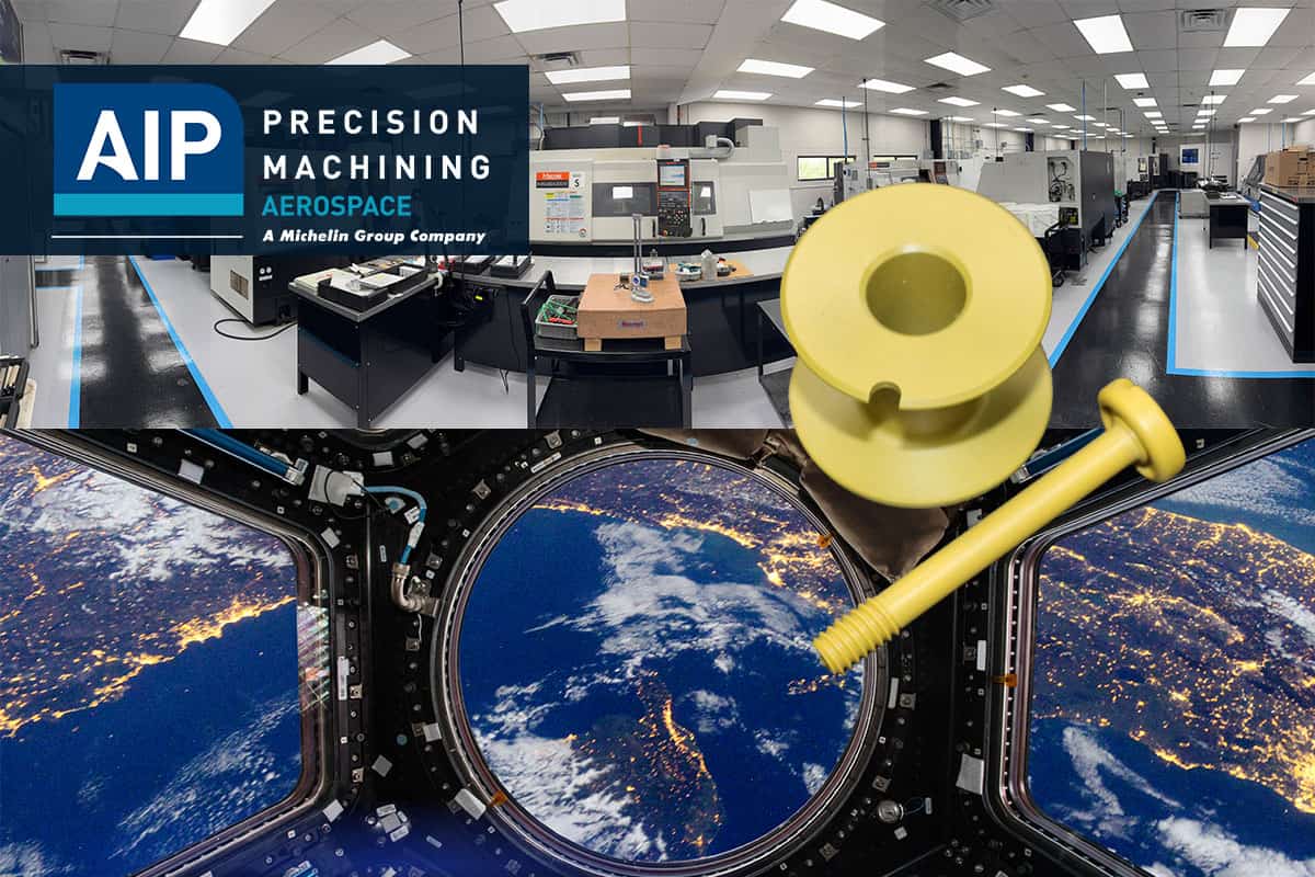
PEEK and TORLON 4203 represent the pinnacle of high-performance thermoplastics for critical aerospace applications. Torlon PAI (polyamide-imide) demonstrates exceptional thermal resistance with continuous use temperatures up to 260°C, significantly outperforming many competing materials. Additionally, PAI nanofibers exhibit filtering efficiency above 90% for particles sized at 0.3 microns, making them ideal for specialized aerospace filtration systems.

When selecting materials for mission-critical aerospace components, engineers must balance multiple performance factors. Torlon bushings maintain their strength and stability in extreme temperature ranges from -40° to 260°C, while also offering excellent chemical resistance against harsh substances commonly found in aerospace environments.

Furthermore, Torlon PAI finds extensive applications in thermal isolators, screws, tubing, and structural components. Both PEEK and Torlon are widely recognized for their exceptional performance in aerospace applications, though each offers distinct advantages depending on specific requirements. This comparative analysis examines the critical performance metrics that determine material selection for high-temperature, high-stress aerospace environments where component failure is not an option.


Why Compare PEEK and TORLON 4203 in Aerospace?

Material selection stands as the foundation of modern aerospace engineering, directly influencing performance, safety, and operational costs. The comparative analysis between PEEK and TORLON 4203 has become increasingly relevant for engineers facing stringent performance requirements in critical applications.


Material selection challenges in high-performance aerospace parts

Aircraft components must perform reliably under extraordinarily challenging conditions. These parts endure extreme temperature fluctuations, exposure to aggressive chemicals, and substantial mechanical stress. Consequently, aerospace engineers face complex material selection decisions requiring meticulous evaluation across multiple performance criteria.

For aerospace applications, materials must maintain structural integrity under temperatures ranging from -40°F (-40°C) to over 500°F (260°C).

Moreover, components frequently encounter jet fuels, de-icing chemicals, and various lubricants throughout their service life. Both PEEK and TORLON 4203 offer exceptional solutions to these challenges, albeit with different performance profiles.


Overview of FAA-compliant plastics for critical components

Regulatory compliance remains paramount in aerospace manufacturing. High-performance polymers used in aircraft applications must meet stringent FAA flammability standards, particularly those specified in FAR 25.853. Many materials undergo continuous testing for flammability, smoke development, and toxicity to ensure they meet these critical safety requirements.

PEEK and TORLON 4203 have established track records of compliance with aerospace industry standards. Both materials appear on Qualified Parts Lists (QPL) for major OEMs including Boeing and Airbus, authorizing their use in demanding structural applications.


Role of high-temperature plastics in aircraft systems

High-temperature polymers have fundamentally transformed aerospace component design. In propulsion systems, TORLON PAI and PEEK deliver exceptional chemical resistance alongside remarkable strength-to-weight ratios. Their unique properties enable innovative system designs that simultaneously reduce weight and cost.

PEEK maintains its mechanical properties at temperatures up to 482°F (250°C), whereas TORLON excels with continuous use temperatures reaching 500°F (260°C). This thermal stability makes them ideal for applications including bushings in blocker door assemblies, screws requiring EMI/RFI transparency, external light housings, and thermal isolators.

Primarily, the choice between these materials depends on specific application requirements.


Head-to-Head Comparison of Key Material Properties

When evaluating high-performance thermoplastics for critical aerospace applications, direct comparison of mechanical, thermal, and chemical properties becomes essential for engineers making material selection decisions.
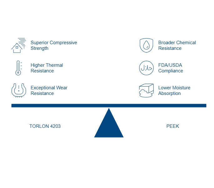
PEEK compressive strength vs TORLON 4203 tensile performance

TORLON 4203 exhibits exceptional compressive strength at 24,000 psi, which is double that of unfilled PEEK and 30% higher than ULTEM PEI. Regarding tensile properties, TORLON 4203 demonstrates impressive performance with a tensile strength of 18,000 psi and a tensile modulus of 600,000 psi.

In contrast, PEEK offers tensile strength of approximately 16,000 psi. Indeed, TORLON maintains superior mechanical properties even at elevated temperatures, retaining its strength and stiffness at temperatures up to 275°C.


Thermal resistance: TORLON max service temperature vs PEEK

The maximum continuous operating temperature for TORLON 4203 reaches 500°F (260°C), slightly outperforming PEEK which operates reliably up to 482°F (250°C). This difference becomes crucial in aerospace applications where components face extreme thermal environments.

Furthermore, TORLON 4203 boasts a heat deflection temperature of 532°F (278°C) at 264 psi, providing excellent dimensional stability under thermal stress.


Moisture absorption and dimensional stability

Notably, TORLON 4203 absorbs 0.4% moisture in 24 hours, which is higher than PEEK. This characteristic requires consideration when designing components for wet environments. At 50% relative humidity and 70°F, TORLON’s water absorption and resultant dimensional growth are 30-40% less even after 400 days.


Wear resistance: TORLON 4203 vs PEEK in dry and lubricated conditions

TORLON 4203 delivers exceptional wear resistance with a limiting PV factor of 12,500 psi × ft/min and a wear factor “k” of 50 × 10^-10 in³-min/ft-lb-hr. The wear resistance is maximized through post-curing after machining, improving limiting PV and wear rate by approximately 5X.


Chemical compatibility with fuels, oils, and hydraulic fluids

TORLON exhibits excellent resistance to a wide range of automotive and aviation fluids, primarily jet fuels, gasoline, and most hydrocarbon-based solvents. PEEK demonstrates broader chemical resistance, especially against acids, bases, and organic solvents. For aerospace applications requiring FDA and USDA purity standards, however, PEEK is often preferred as TORLON does not meet these specific requirements.


Flammability ratings and outgassing behavior in aerospace

From a safety perspective, TORLON 4203 achieves a UL94 V-0 flammability rating with low smoke generation. Both TORLON PAI and PEEK qualify as low-outgassing materials with Total Mass Loss (TML) levels below 1% and Collected Volatile Condensable Material (CVCM) less than 0.1%, meeting NASA’s stringent requirements for spacecraft materials.


Application-Specific Use Cases in Aerospace Systems

Both PEEK and TORLON 4203 excel in specific aerospace applications, addressing unique design challenges through their distinctive performance characteristics.


PEEK components for aircraft systems: tubing, seals, and housings

PEEK tubing serves multiple functions across aerospace systems, primarily acting as protective sheathing and fluid transfer conduits for high-temperature fluids. Its exceptional strength-to-weight ratio makes it particularly valuable for HPLC pressure applications, effectively replacing heavier stainless steel components. PEEK seals control liquid and gas flow in valves, compressors, and blowout preventers, remaining chemically stable when exposed to aviation fluids. Additionally, valve seats manufactured from PEEK maintain their rigidity despite continuous exposure to hot water and steam.


TORLON 4203 parts: bushings, valve seats, and structural brackets

Torlon 4203 represents the toughest and most impact-resistant Torlon grade, making it ideal for highly loaded wheels, rollers, and balls. In aerospace applications, Torlon 4203 excels in valve seats requiring dimensional stability, thermal insulators, and electrical components demanding heat resistance and low flammability. Specifically, F-16 fighter aircraft utilize Torlon 4203 for fuel connectors in auxiliary tanks, withstanding pressures beyond 650 psi while resisting jet fuel exposure.


Suitability for high-altitude and cryogenic environments

PEEK demonstrates remarkably low water absorption (0.03%) and minimal outgassing in vacuum environments, making it suitable for high-altitude aerospace applications. Conversely, Torlon maintains excellent properties under cryogenic conditions without becoming brittle like other resins. Both materials provide reliable performance at extreme altitudes where temperature fluctuations are severe.


Performance in fuel-exposed and high-vibration zones

PEEK bushings in blocker door assemblies deliver precise performance across temperature ranges from -40°F to 500°F without lubrication. For vibration-intensive environments, Torlon 4203 maintains dimensional integrity while exposed to continuous vibration in fuel connectors.


Precision Machining and Certification Considerations

Precision manufacturing remains paramount in aerospace applications where component failure is not an option. For high-performance plastics like PEEK and TORLON 4203, specialized machining expertise ensures optimal performance in mission-critical applications.


AS9100D certified machining for aerospace-grade plastics

Aerospace manufacturing demands adherence to AS9100D certification, which builds upon ISO 9001:2015 by adding specifications tailored explicitly for aviation, space, and defense organizations.

This stringent standard requires implementation of risk mitigation processes, strict configuration management, and comprehensive validation procedures. Accordingly, certified manufacturers maintain complete traceability records for a minimum of 10 years, ensuring accountability throughout the production process.


±0.002 mm tolerances in tight tolerance plastic parts

Premium aerospace manufacturers achieve tolerances as tight as ±0.002 mm, essential for components where precision directly impacts flight safety.

During their service life, such tight-tolerance parts maintain dimensional stability even after thermal cycling. Precision machining within climate-controlled environments ensures these exacting standards are met consistently, primarily for complex geometries across varied thermoplastic materials.


DFM for engineered plastic parts in aircraft

Design for manufacturability in aerospace plastic components requires avoiding metal machining companies regardless of their experience, as the contamination risk is too high.

Furthermore, PEEK machining demands specific tooling approaches: carbide tooling for short production runs and polycrystalline diamond tooling for tight-tolerance parts.


Rapid prototyping of custom TORLON and PEEK parts

Short-run prototype parts can be produced using aluminum prototype tooling, low-cavity steel molds, or even 3D printed tooling inserts where appropriate. This approach allows validation of designs before investing in full production tooling.

Partner With a Certified Leader in Aerospace Polymer Machining From material selection to mission-critical part production, AIP Precision Machining brings over 40+ years of experience and AS9100D-certified precision to your aerospace programs.


Conclusion

PEEK and TORLON 4203 remain essential high-performance thermoplastics in aerospace component design, each excelling in different performance domains. TORLON 4203 offers unmatched compressive strength and superior dimensional stability at elevated temperatures, making it the material of choice for high-load, high-heat applications such as fuel connectors, valve seats, and structural brackets.

On the other hand, PEEK presents key advantages in applications requiring low moisture absorption, chemical resistance, and long-term performance in aggressive environments. Its ability to maintain structural integrity in high-humidity or chemically exposed systems—combined with its low outgassing and compliance with FDA/USDA standards—makes it indispensable in aerospace fluid management and electrical insulation applications.

The optimal choice between these two materials depends on precise application demands. Aerospace engineers must assess a balance of thermal resistance, wear performance, chemical compatibility, and environmental exposure. Regardless of material, precision manufacturing is critical—particularly for flight-critical components requiring tolerances as tight as ±0.002 mm.


Partner With a Certified Aerospace Machining Expert

Whether you’re specifying bushings, thermal isolators, or EMI-safe connectors, AIP Precision Machining offers AS9100D-certified expertise, polymer-only machining, and over 40+ years of experience supporting mission-critical aerospace programs. Contact us for consultation on your next PEEK or TORLON application—from rapid prototyping to full-scale production.


FAQs

Q1. How does PEEK compare to TORLON 4203 in aerospace applications?

PEEK and TORLON 4203 are both high-performance thermoplastics used in aerospace, each with distinct advantages. TORLON 4203 excels in compressive strength and thermal resistance, while PEEK offers better moisture resistance and chemical compatibility. The choice between them depends on specific application requirements.


Q2. What are the key advantages of TORLON 4203 in aerospace components?

TORLON 4203 offers exceptional compressive strength, superior mechanical properties at high temperatures, and excellent wear resistance. It’s ideal for highly loaded wheels, valve seats requiring dimensional stability, and fuel connectors that need to withstand high pressures in extreme environments.


Q3. In which aerospace applications does PEEK excel?

PEEK is particularly suitable for protective tubing, seals controlling liquid and gas flow, and components exposed to various chemicals. It also performs well in high-altitude applications due to its low water absorption and minimal outgassing in vacuum environments.


Q4. What certifications are important for aerospace plastic machining?

AS9100D certification is crucial for aerospace manufacturing. It builds upon ISO 9001:2015 by adding specifications for aviation, space, and defense organizations. This certification ensures strict quality control, risk mitigation, and traceability in the production process.


Q5. How tight are the tolerances achievable in aerospace plastic parts?

Premium aerospace manufacturers can achieve tolerances as tight as ±0.002 mm for plastic parts. This level of precision is essential for components where dimensional accuracy directly impacts flight safety and performance. Specialized machining expertise and climate-controlled environments are necessary to consistently meet these exacting standards.

Follow AIP Precision Machining on Linkedin

linkedin logo

ULTEM® aerospace parts play a vital role in the industry because of their exceptional performance characteristics. ULTEM® stands out as one of the few resins with approval for aerospace applications. This 30-year old material powers flight-critical components. Our team at AIP Precision Machining has supplied ULTEM® components to aircraft OEM and MRO providers of all sizes worldwide.

Engineers and procurement specialists need to know the differences between ULTEM® 1000 and ULTEM® 2300 for aerospace applications. ULTEM® 1000, the standard unfilled polyetherimide product, shows impressive strength that goes beyond 1300MPa at room temperature. ULTEM® 2300, with its 30% glass fiber reinforcement, reaches around 2100MPa. The material’s heat distortion temperature sits at 204°C at 264 psi. This makes it perfect for high-temperature aerospace environments. The material stays strong under repeated mechanical stress and meets FAA’s strict flammability regulations.


Key Takeaways

Understanding the critical differences between Ultem® 1000 and 2300 enables aerospace engineers to make informed material selections for mission-critical components based on specific performance requirements.

• Ultem® 1000 excels in electrical applications with superior dielectric strength (830 V/mil) and transparency, making it ideal for avionics housings and electrical insulators.
• Ultem® 2300 provides superior structural performance with 30% glass reinforcement delivering 850,000 psi flexural modulus versus 500,000 psi for Ultem® 1000.
• Thermal expansion differs significantly – Ultem® 2300’s coefficient (1.1 x 10^-5 in/in/°F) matches aluminum, while Ultem® 1000 expands nearly 3x more.
• Machining requirements vary between grades – Ultem® 1000 offers easier machinability, while glass-filled Ultem® 2300 requires specialized tooling and lower speeds.
• Both materials meet stringent aerospace standards including FAA flammability regulations, low outgassing for space applications, and resistance to aviation fluids.

The key decision factor: Choose Ultem® 1000 for electrical insulation and weight-sensitive applications, select Ultem® 2300 for structural components requiring maximum rigidity and dimensional stability under load.


Ultem® 1000 and 2300: Material Overview and Composition

Polyetherimide (PEI), sold under the Ultem® trademark, stands as a breakthrough in high-performance engineering thermoplastics. General Electric introduced this remarkable material in 1982, and it quickly became essential for aerospace applications that need top-notch thermal stability and mechanical strength.

Ultem® 1000: Unfilled PEI for General Aerospace Use

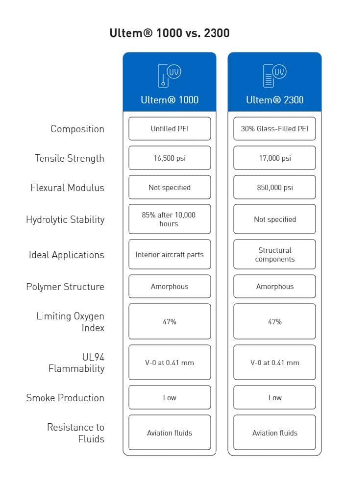
Ultem® 1000 serves as the standard unfilled grade of polyetherimide – you can call it the “virgin” or “neat” resin without additives. This amber-colored, transparent thermoplastic shows impressive mechanical strength that tops 16,500 psi. The material’s excellent hydrolytic stability helps it keep 85% of tensile strength even after 10,000 hours in boiling water. Ultem® 1000 works best where flame resistance, electrical insulation, and chemical stability matter most, making it perfect for interior aircraft parts.


Ultem® 2300: 30% Glass-Filled PEI for High-Rigidity Applications

Ultem® 2300 takes things further by adding 30% glass fiber reinforcement to boost its mechanical properties. This addition lifts tensile strength to about 17,000 psi and flexural modulus to 850,000 psi, which means better dimensional stability than Ultem® 1000. Ultem® 2300’s ability to handle high tensile loads makes it ideal for structural components that face serious mechanical stress in aerospace applications.


Ultem® Polymer Structure and Amorphous Behavior

PEI’s repeating unit has a molecular formula of C₃₇H₂₄O₆N₂ with a molecular weight of 592.61 g/mol. Ultem® differs from semi-crystalline polymers because it’s completely amorphous and contains phthalimide and bisphenol A sub-units. This amorphous structure creates isotropic behavior and reliable dimensional stability across different temperatures. The material’s glass transition temperature reaches 217°C (421°F), which explains its great mechanical properties at high temperatures.


Ultem® Material Properties Relevant to Aerospace

Aerospace engineers value Ultem®’s mix of high strength-to-weight ratio and thermal stability. Both grades deliver outstanding flame resistance with a limiting oxygen index of 47% and meet UL94 V-0 specifications in sections as thin as 0.41 mm. The materials produce very little smoke during combustion, which is crucial for aircraft interior safety. Ultem® also resists aviation fluids well, including jet fuel and hydraulic fluids, and stays strong in these tough operating conditions.


Side-by-Side Performance Metrics for Aerospace Engineers

Aerospace engineers need reliable data to pick the right materials for flight-critical components. Here is a side by side comparison of Ultem® 1000 and 2300:

Performance Category Ultem® 1000 (Unfilled PEI) Ultem® 2300 (30% Glass-Filled PEI)
Tensile Strength 16,500 psi 17,000 psi
Flexural Modulus 500,000 psi 850,000 psi
Thermal Expansion 3.1 × 10⁻⁵ in/in/°F 1.1 × 10⁻⁵ in/in/°F (similar to 6061-T6 aluminum)
Heat Deflection Temp (264 psi) 400°F (204°C) 410°F (210°C)
Dielectric Strength 830 V/mil (higher electrical insulation) 770 V/mil
Surface Resistivity > 10¹³ ohms/square > 10¹³ ohms/square
Weight Considerations Lower density; ideal for lightweight applications Heavier; optimized for strength and rigidity
Machinability Easier to machine; less tool wear More abrasive; requires specialized tooling
Ideal Aerospace Use Cases Avionics housings, electrical insulators, covers Structural brackets, load-bearing components


Tensile Strength and Flexural Modulus Comparison

The tensile strength numbers tell an interesting story. Ultem® 1000 delivers 16,500 psi, and Ultem® 2300 comes in at 17,000 psi. This small difference matters a lot for parts under heavy loads. The flexural modulus shows an even bigger gap – Ultem® 1000 reaches 500,000 psi while Ultem® 2300 hits 850,000 psi. Glass-reinforced Ultem® 2300 proves much better for structural parts that need to resist bending forces.


Thermal Expansion and Heat Deflection Differences

Let’s look at how these materials handle heat. Ultem® 1000’s coefficient of linear thermal expansion is 3.1 x 10^-5 in/in/°F, while Ultem® 2300 comes in at 1.1 x 10^-5 in/in/°F. Ultem® 2300’s thermal expansion matches 6061-T6 aluminum closely, making it perfect for replacing metal parts. The heat deflection temperature at 264 psi shows Ultem® 1000 stays stable up to 400°F (204°C). Ultem® 2300 edges slightly ahead at 410°F (210°C).


Electrical Insulation and Dielectric Strength

Both materials excel at electrical insulation. Ultem® 1000 leads the pack with one of the highest dielectric strengths among thermoplastics at 830 V/mil. Ultem® 2300 follows closely at 770 V/mil. Both materials show surface resistivity above 10^13 ohms/square, which means excellent insulation properties at any frequency.


Weight vs Strength Tradeoffs in Ultem® 1000 Aerospace Parts

Ultem® 2300 might have better mechanical properties, but Ultem® 1000 shines in aerospace applications where weight matters most. Ultem® 1000 matches the strength of filled thermoplastics and adds transparency as a bonus. Its molecular chain flexibility helps absorb impact energy without breaking. This feature proves crucial for parts that might take occasional hits.


CNC Machining Considerations for Ultem® 1000 vs 2300

At AIP Precision, our polymer-exclusive facility specializes in machining Ultem® materials for aerospace applications. Our specialized techniques achieve the highest precision levels. The contamination-free processing we provide will give a solid foundation for flight-critical components.


Chip Formation and Toolpath Optimization

Ultem® creates long, thin chips during machining that might clog cutting tools without proper management. Our team uses tools with high rake angles and optimized chipbreakers to promote quick chip evacuation for Ultem® 1000. High helix end mills work best with Ultem® 2300 because its glass reinforcement produces more abrasive chips that need better management. The team must remove scrap continuously to prevent surface scratches and internal stresses.


Machining-Induced Stress and Warpage

Stress-relieving through annealing helps prepare Ultem® materials before machining. This step reduces surface cracks and internal stresses. Our process for Ultem® 2300 includes post-machining annealing at 300°F to 400°F (150°C to 200°C) for several hours. The material cools slowly afterward. These steps stabilize material dimensions and relieve machining-induced stresses.


Surface Finish Quality in Tight-Tolerance Parts

Tool selection affects surface quality heavily in aerospace components that need precise tolerances. Both grades require sharp carbide tools because of Ultem®’s abrasive nature. Our team switches to a “polishing knife” during the final 0.1mm light cutting process for Ultem® 2300. This approach helps us control surface roughness within Ra < 1.6 μm and meet aerospace industry standards.


Material Removal Rate and Feed Rate Adjustments

Each material needs different cutting parameters. Ultem® 1000 works best at speeds of 800-1200 rpm. Glass-reinforced Ultem® 2300 needs lower speeds of 600-1000 rpm to prevent thermal expansion. Feed rates should stay between 0.05-0.12 mm/rev. Light cuts of 0.3-0.5mm during finishing help maintain geometric accuracy.

AIP brings over 40 years of experience in machining advanced polymers exclusively. We help aerospace teams reduce risk, speed up timelines, and ensure compliance. Our AS9100-certified machining of Ultem® 1000 or Ultem® 2300 delivers high-performance aerospace components with tight tolerances. Contact us today to review your design or request a precision quote.


When to Choose Ultem® 1000 or 2300 for Aerospace Applications

Choosing between Ultem® 1000 and 2300 depends on your aerospace application’s specific needs.


Avionics Housings and Electrical Insulators

Avionics housings and electrical components benefit from Ultem® 1000’s exceptional dielectric strength of 830 V/mil, which makes it the top choice. Ultem® 1000’s volume resistivity is a big deal as it means that it exceeds 10^13 ohms/square, delivering superior electrical insulation across wide frequency ranges. The unfilled Ultem® 1000 stands out when applications need low electrical conductivity and UV radiation resistance. This makes it perfect for sensor housings, electrical connectors, and circuit board components.


Thermal Insulators and Fluid System Components

Ultem® 1000 retains 85% of its tensile strength after 10,000 hours in boiling water, which proves excellent for fluid system components. Notwithstanding that, Ultem® 2300 shows better results in high-temperature fluid systems with its higher heat deflection temperature of 410°F (210°C).

Both materials resist aviation fluids effectively and maintain their structural integrity in fuel systems.


Structural Brackets and Load-Bearing Supports

Ultem® 2300’s 30% glass fiber reinforcement delivers a tensile strength of approximately 2100MPa compared to Ultem® 1000’s 1300MPa. Structural brackets under mechanical stress benefit from Ultem® 2300’s enhanced rigidity. This becomes clear in its flexural modulus of 850,000 psi versus Ultem® 1000’s 500,000 psi. Ultem® 2300 can replace aluminum in structural applications because its thermal expansion coefficient matches 6061-T6 aluminum.


Ultem® Space Applications: Outgassing and Stability

These grades show low outgassing properties, and Ultem® 9085 (a variant) shows remarkably low CVCM values of 0-0.1%. Space applications benefit from Ultem® because outgassing could contaminate sensitive optics or electronics. The material works well in orbital applications due to its dimensional stability under extreme temperature changes.


Precision Plastics Machining for Mission-Critical Parts

Precision-machined components work better with Ultem® 1000 as it causes less tool wear. Ultem® 2300 needs specialized tooling because of its glass fiber abrasiveness.


Conclusion

This piece explores the key differences between Ultem® 1000 and Ultem® 2300 for aerospace applications. These high-performance polymers are a great way to get the right properties for flight-critical components, each with distinct advantages for specific uses.

Ultem® 1000’s unfilled PEI composition delivers superior electrical insulation, making it perfect for avionics housings and components that need excellent dielectric strength. It also offers transparency, impact resistance, and better machinability – clear advantages for many aerospace applications.

The glass fiber reinforcement in Ultem® 2300 makes it excel in structural applications. This boost increases flexural modulus and tensile strength by a lot while bringing thermal expansion down to aluminum-like levels. Aerospace engineers should pick this variant when designing load-bearing brackets and components under mechanical stress.

Both materials showcase remarkable thermal stability, chemical resistance, and flame retardancy – vital properties in aerospace environments. Your specific application needs will determine the choice between these exceptional polymers, whether you need electrical insulation or structural support, lighter weight or maximum rigidity.
AIP Precision’s four decades of experience have taught us these subtle differences through machining these advanced polymers to aerospace specifications. Our polymer-exclusive facility will give a contamination-free processing environment with ±0.002 mm tolerances under AS9100 certification. We use specialized techniques like optimized toolpaths and post-machining annealing to deliver top-quality Ultem® components.

As someone who works closely with aerospace engineers and sourcing managers every day, I’ve seen firsthand how the right material selection impacts long-term performance and program success. Whether you’re deciding between Ultem® 1000 for its electrical insulation or Ultem® 2300 for structural reinforcement, AIP can support your team from concept to final part. If you have questions about which Ultem® grade is right for your aerospace application, feel free to reach out. — Fred Castro, Project Specialist, AIP Precision Machining.


FAQs

Q1. What are the main differences between Ultem® 1000 and Ultem® 2300?
Ultem® 1000 is an unfilled polyetherimide (PEI) with superior electrical properties, while Ultem® 2300 contains 30% glass fiber reinforcement for enhanced mechanical strength. Ultem® 1000 excels in electrical insulation, while Ultem® 2300 is better suited for structural applications requiring high rigidity.


Q2. Which Ultem® grade is better for aerospace structural components?
Ultem® 2300 is generally preferred for aerospace structural components due to its higher flexural modulus (850,000 psi) and tensile strength. Its glass fiber reinforcement provides greater rigidity and dimensional stability under mechanical stress, making it ideal for load-bearing brackets and supports.


Q3. How do Ultem® 1000 and 2300 compare in terms of thermal properties?
Both materials offer excellent thermal stability, but Ultem® 2300 has a slightly higher heat deflection temperature (410°F/210°C) compared to Ultem® 1000 (400°F/204°C). Notably, Ultem® 2300’s thermal expansion coefficient is closer to that of aluminum, making it suitable for metal replacement in certain applications.


Q4. Are there any machining differences between Ultem® 1000 and 2300?
Yes, there are significant machining differences. Ultem® 1000 is generally easier to machine with less tool wear. Ultem® 2300, due to its glass fiber content, requires specialized tooling and lower machining speeds to manage the abrasiveness of the material and maintain surface quality.


Q5. How do these materials perform in terms of flame resistance and chemical stability?
Both Ultem® 1000 and 2300 exhibit excellent flame resistance, meeting UL94 V-0 specifications and FAA flammability regulations. They also demonstrate high chemical stability, maintaining integrity when exposed to aviation fluids, including fuel and hydraulic fluids, making them suitable for various aerospace applications.

Follow AIP Precision Machining on Linkedin

linkedin logo

The aerospace industry now accounts for nearly 16% of the total revenue generated by the additive manufacturing industry. Precision 3D printers have achieved remarkable milestones, exemplified by Relativity Space launching the world’s first 3D-printed rocket in March 2023. Despite these advancements, 3D printing technology still faces significant challenges, including high costs, low printing speeds, limited part sizes, and strength issues.

While different 3D printing technologies offer varying capabilities regarding tolerances—such as MJF at ±0.3% (±0.2 mm), SLS at ±0.3% (±0.3 mm), SLA at ±0.5% (±0.2 mm), and FDM at ±0.5% (±0.5 mm)—they all struggle with fundamental limitations. This variance becomes particularly problematic in highly regulated industries like aerospace and medical device manufacturing, where even slight dimensional inaccuracies can have serious consequences.

Although processes like SLA provide fine finishes and high accuracy, materials undergo shrinkage during curing, creating internal stresses that affect dimensional accuracy. This article examines why even the most advanced 3D printing systems fall short in meeting the stringent requirements of regulated manufacturing environments, and how hybrid manufacturing approaches combining additive and subtractive methods offer a more viable solution.


Dimensional Tolerance Challenges in Precision 3D Printing

Dimensional accuracy remains a significant challenge for manufacturers relying on additive technologies, even with the most sophisticated equipment available. Resolution specifications alone fail to guarantee accurate parts, as multiple factors affect the final dimensional accuracy of printed components.

Inconsistent tolerances in FDM vs SLA vs DMLS

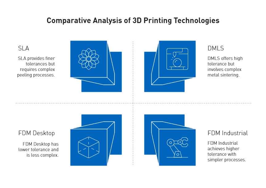
Each 3D printing technology offers notably different tolerance capabilities. FDM systems typically achieve tolerances of ±0.5% (lower limit: ±0.5 mm) for desktop printers and ±0.15% (lower limit: ±0.2 mm) for industrial machines. Furthermore, FDM parts frequently suffer from warping and shrinkage as layers cool at different rates, creating internal stresses that deform prints.

In contrast, SLA technology produces finer tolerances of approximately ±0.2% (lower limit: ±0.1 mm). However, the peeling process during printing can introduce dimensional inaccuracies as pulling forces cause soft prints to bend slightly.

DMLS offers tolerances of ±0.2% (lower limit: ±0.1-0.2 mm), yet the high heat involved in metal sintering often leads to shrinkage issues that must be compensated for in design.


3D printing tolerance for moving parts and assemblies

Achieving functional assemblies with precision 3D printers requires specific clearance considerations. For proper fit between components, manufacturers typically apply clearance gaps of 0.005″ (0.127 mm) for tight fits, 0.010″ (0.254 mm) for normal fits, and 0.020″ (0.508 mm) for loose fits.

Additionally, holes in 3D printed parts consistently print undersized due to limitations of the STL file format, which builds circles from straight-edged triangles. This characteristic necessitates accounting for these deviations when designing critical features.


Impact of anisotropic properties on part accuracy

Layer-by-layer fabrication inherently creates anisotropic characteristics in printed components. Mechanical testing reveals that build orientation significantly influences final properties, with parts built in upright orientation demonstrating especially poor performance.

Research confirms that raster direction substantially affects fracture behavior in FDM parts. For instance, SLA parts printed in 90° orientation exhibit greater strength but increased brittleness compared to other orientations because previously cured layers receive additional laser exposure.

This orientation-dependent performance becomes particularly problematic in regulated industries where consistent mechanical properties are essential across all dimensions. Consequently, the anisotropic nature of 3D printed parts often necessitates subsequent machining operations to achieve the uniform properties and tight tolerances required for aerospace and medical applications.


Material and Surface Limitations in Regulated Applications

Surface finish stands as a fundamental barrier to widespread adoption of additive manufacturing in regulated industries. Surface roughness, a critical quality indicator, directly impacts mechanical, physical, and tribological properties of printed components.


Surface roughness and porosity in aerospace-grade polymers

Internal porosity poses a significant challenge in 3D printed parts, as these invisible voids reduce component density and potentially lead to cracks, leaks, and fatigue. Recent innovations at Oak Ridge National Laboratory have demonstrated that vacuum-assisted extrusion can reduce internal porosity by up to 75% in large-scale polymer prints. This advancement is crucial given that surface irregularities disrupt boundary layer flow and accelerate the transition from laminar to turbulent flow, particularly in aerospace applications such as UAV propellers.

Moreover, surface roughness values vary dramatically between materials and printing technologies. For instance, PLA exhibits higher arithmetic mean roughness values (16.2-17.6 μm) compared to PETG (9.0-10.8 μm) in standard quality prints. These variations significantly influence functional performance, with rougher surfaces leading to enhanced aerodynamic drag and irregular airflow patterns.


Limitations of PEEK additive manufacturing for FDA-compliant parts

PEEK, despite its popularity in medical applications, presents substantial manufacturing challenges. Its high melting temperature, semi-crystalline structure, and significant cooling shrinkage rate increase process complexity and result in uncontrollable properties of 3D-printed parts. Indeed, the crystallization properties of PEEK are greatly affected by thermal history, requiring precise control of printing temperature, ambient temperature, and heat treatment conditions.

Another major obstacle lies in PEEK’s biological inertness, which hinders integration with bone and soft tissue—a critical requirement for medical implants. For dental applications specifically, printing high-resolution small structures (<15 mm) with fine threads proves extremely challenging, primarily because extruding PEEK through small diameter nozzles (<0.2 mm) is difficult due to the polymer’s high melt viscosity.


Post-processing requirements for biocompatible components

Biocompatibility certifications necessitate rigorous post-processing protocols. For instance, to achieve compliance with ISO 10993-5:2009 (cytotoxicity), ISO 10993-10:2021 (sensitization), and ISO 10993-23:2021 (irritation) standards, parts must undergo specific washing and curing processes. Typically, this involves multiple wash cycles in IPA or ethanol, followed by air drying and thermal curing.

File transfer also poses regulatory challenges, as the FDA expresses concerns about consistency across file formats. The ability to verify initial design intent throughout the manufacturing process is essential for traceability and audit purposes. Consequently, post-processing becomes a critical consideration for manufacturers seeking to produce FDA-compliant components.


Why Precision Alone Isn’t Enough for Regulated Manufacturing

Regulated manufacturing environments demand more than just dimensional accuracy from production methods. Precise tolerances serve as merely one aspect of a comprehensive quality system that must satisfy rigorous industry standards.


AS9100 and ISO 13485 compliance requirements

Beyond precise dimensions, AS9100 (aerospace) and ISO 13485 (medical devices) certifications require exhaustive documentation of all manufacturing processes. These standards necessitate controlled procedures, risk management protocols, and regular internal audits. For instance, ISO 13485 mandates complete product identification throughout manufacturing, thorough validation of all processes, and strict control of nonconforming products. Similarly, AS9100 requires detailed first article inspection reports documenting 100% of product characteristics.


Traceability and repeatability in medical device manufacturing

Medical device manufacturing mandates unbroken traceability from raw material to finished product. Every component must be traceable to its manufacturing batch, machine parameters, and operator. Nevertheless, 3D printing creates challenges in this domain as material properties can vary substantially between print jobs due to environmental factors like ambient humidity or temperature fluctuations. These variations undermine the consistency required for validated medical manufacturing processes.


Limitations of 3D printing in achieving validated processes

Process validation, a cornerstone requirement in regulated manufacturing, demands that manufacturers prove their processes consistently produce the same results. Unfortunately, additive manufacturing processes face inherent difficulties achieving this standard. Factors including thermal history, layer adhesion variability, and support structure removal introduce unpredictability that complicates validation efforts. Therefore, while precision 3D printers excel at creating complex geometries, they rarely satisfy the stringent validation requirements of regulated environments without substantial post-processing and secondary operations.


Hybrid Manufacturing: Bridging the Gap with CNC Machining

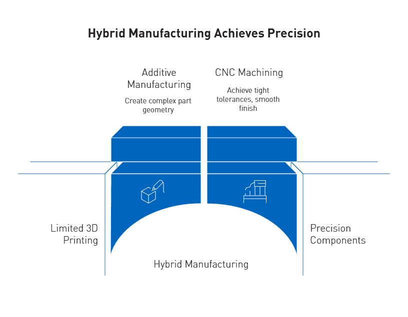
Hybrid manufacturing is a practical solution that combines the complex geometry capabilities of additive manufacturing with the superior surface finish and tight tolerances of precision machining. This integrated approach effectively addresses the fundamental limitations of standalone 3D printing systems.

Subtractive finishing of 3D printed parts for tight tolerances

Hybrid processes enhance dimensional accuracy dramatically—from Ra30μm in selective laser melting to Ra0.4μm after CNC finishing. Ultimately, this approach enables components to meet the micron-level tolerances required for critical applications. While precision 3D printers typically achieve tolerances around 0.1 mm, CNC machining elevates this to 0.025 mm, making hybrid manufacturing ideal for moving parts and assemblies.


Machined PEEK components for aerospace and medical use

PEEK stands out as an exceptional polymer for regulated applications, offering remarkable properties:

  • Maintains flexural and tensile properties at temperatures exceeding 482°F
  • Withstands over 1,500 steam autoclave cycles without significant degradation
  • Demonstrates exceptional resistance to wear, heat, and radiation

These characteristics make machined PEEK components essential for critical aerospace and medical applications where thermal, chemical, and combustion properties are paramount.


AIP’s polymer-only expertise and certified hybrid workflows

Operating under ISO 13485:2016 compliance with FDA registration status, AIP has achieved tolerance capabilities reaching ±0.002 mm. By exclusively machining plastics, they eliminate metallic cross-contamination risk—vital for biocompatible applications where material purity directly impacts patient safety.

Ready to bridge the gap between additive innovation and certified performance? Partner with AIP Precision Machining to transform your precision 3D printed parts into mission-critical components that meet the highest regulatory and engineering standards. Contact AIP’s engineering team today to discuss hybrid manufacturing solutions built for compliance, consistency, and performance.


Conclusion

Precision 3D printers have advanced rapidly, offering new possibilities in design complexity and rapid prototyping. However, when it comes to regulated manufacturing environments—where compliance, repeatability, and micron-level tolerances are non-negotiable—additive alone isn’t enough.

Across all major 3D printing technologies, issues like dimensional variability, anisotropic mechanical properties, and rough surface finishes continue to challenge part consistency. Materials such as PEEK, ideal for aerospace and medical applications, become difficult to control during additive processing due to shrinkage, crystallization, and thermal instability.

More critically, certifications like AS9100 and ISO 13485 require validated processes, traceability, and consistent outcomes—criteria that additive methods often fail to meet without secondary operations.

This is where hybrid manufacturing provides a decisive advantage. By combining the design freedom of additive with the precision, surface finish, and process control of CNC machining, manufacturers can meet both engineering and regulatory demands.

At AIP Precision Machining, we specialize in this integrated approach. With over 40 years of experience in polymer-only machining, and certified processes for high-performance plastics, we help clients turn printed parts into production-ready, regulation-compliant components.

Follow AIP Precision Machining on Linkedin

linkedin logo