Creep resistant plastics are essential materials for engineers designing components that must maintain dimensional stability under constant stress. Creep, defined as the change in length or shape over an extended period of time due to continuously applied static stress, occurs when polymer molecules rearrange and flow over time when subjected to constant stress. This phenomenon can be detrimental to the function of products across multiple industries, particularly in applications where precise dimensions must be maintained throughout a component’s service life.
Understanding creep in polymers is therefore crucial for material selection and design, as it directly affects performance, safety, and lifespan. For example, polymers with larger side groups demonstrate less relative mobility than those with small side groups and consequently exhibit lower creep and stress relaxation. Importantly, creep can be categorized into three distinct stages: primary, secondary, and tertiary, each presenting different challenges for load bearing plastics. High-performance engineering materials like PEEK combine excellent mechanical strength and dimensional stability with outstanding resistance to harsh chemicals and superior creep resistance. However, the behavior of these materials varies significantly based on application conditions, with temperature being a major factor, increasing the temperature of a material is commonly used to accelerate the creep rate of polymers.
Understanding Creep in High-Load Polymer Applications
Polymer materials exhibit distinct deformation behaviors under sustained loads that engineers must account for in high-performance applications. Understanding these behaviors allows for proper material selection in demanding environments.
Definition of Creep in Polymers
Creep refers to the gradual, time-dependent deformation of polymer materials when subjected to constant stress over extended periods. Unlike linear elastic materials that show predictable behavior, polymers demonstrate complex deformation patterns. This slow deformation process can occur even when stresses remain well below a material’s yield point. Creep in polymers primarily results from sliding of individual polymer chains relative to one another, with amorphous polymers typically exhibiting greater susceptibility than crystalline variants.
Time-Dependent Deformation Under Constant Load
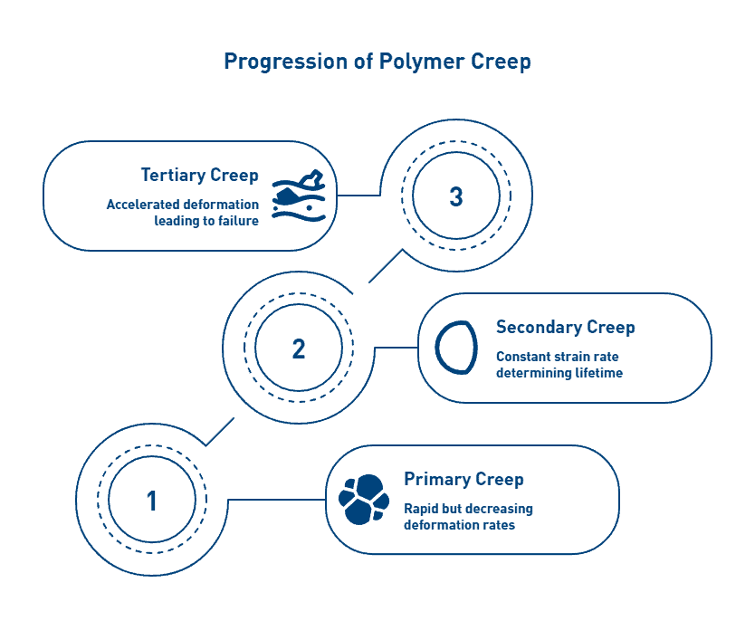
The creep process in polymers typically progresses through three distinct phases. Initially, primary creep occurs, characterized by rapid but decreasing deformation rates. Subsequently, secondary creep follows with a relatively constant strain rate, as this phase often determines a component’s usable lifetime. Finally, tertiary creep involves accelerated deformation that ultimately leads to material failure.
The deformation response includes both instantaneous elastic deformation and progressive permanent creep deformation. After load removal, only partial elastic recovery occurs, with permanent deformation remaining, a phenomenon known as hysteresis. Additionally, temperature dramatically influences creep behavior; higher temperatures increase molecular mobility, thereby accelerating deformation rates.
Why Creep Matters in Structural and Load-Bearing Plastics
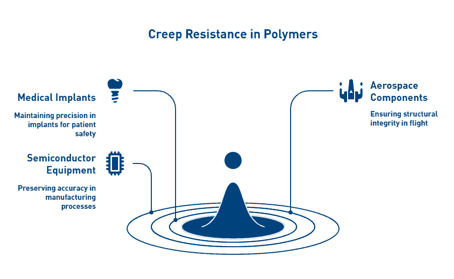
Creep resistance becomes crucial in applications where polymers support continuous loads while maintaining dimensional stability. Furthermore, creep can lead to stress redistribution, prestress loss, and eventually structural failure in critical components. This phenomenon presents special challenges in medical implants, aerospace components, and semiconductor manufacturing equipment where precise dimensions must be maintained throughout service life.
The severity of creep deformation depends primarily on three factors: time under load, stress intensity, and operating temperature. Although metals also experience creep, the behavior is markedly more pronounced in polymers. Engineers must account for this behavior during material selection, especially for components that will experience elevated temperatures while supporting mechanical loads.
Key Factors That Influence Creep Resistance
Several interconnected factors determine a material’s resistance to creep deformation, which engineers must consider when selecting polymers for critical load applications.
Effect of Temperature on Polymer Chain Mobility
Temperature fundamentally affects creep behavior by altering polymer chain mobility. As temperature rises, polymer chains gain kinetic energy and spacing between molecules increases, enabling chains to slide past one another more readily. Studies show that increasing temperature from 20°C to 50°C can increase creep strain by 2.15 times, while at 80°C this factor jumps to 3.93. This temperature dependence occurs because heat reduces intermolecular forces, subsequently accelerating creep rates according to the power-law creep equation. Accordingly, engineers must design with the maximum operating temperature in mind rather than average conditions.
Stress Duration and Load Intensity
Time under load remains a primary factor influencing creep deformation, longer exposure periods result in greater permanent deformation. The relationship between stress and creep follows non-linear patterns, with higher stresses producing proportionally greater deformation rates. Notably, polymers can exhibit creep even at stress levels well below their yield point, making this consideration essential for long-term applications. Besides duration, load intensity directly influences creep rate, with stress-dependent behavior following exponential relationships rather than linear ones.
Role of Crystallinity and Molecular Weight
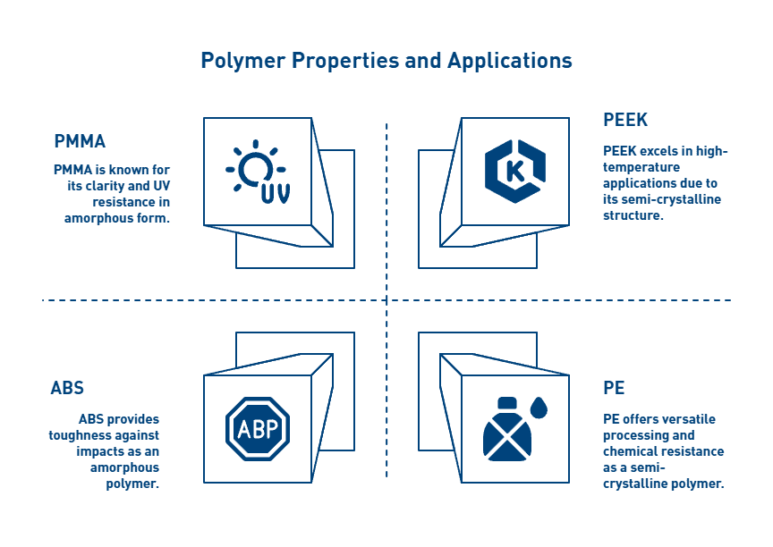
Polymer microstructure profoundly impacts creep resistance. Semi-crystalline polymers generally demonstrate superior creep resistance compared to amorphous variants. Recent research shows that microstructures with larger crystal grains exhibit markedly improved resistance to molecular rearrangement. Furthermore, molecular weight directly correlates with creep resistance, higher molecular weight polymers form more entanglements between chains, restricting molecular motion. Studies indicate that polymers with molecular weights above 1.5 × 10^6 g/mol show significantly improved creep performance.
Impact of Fillers and Reinforcements
Incorporating reinforcing fillers substantially enhances creep resistance. Glass fiber additions of just 30% can improve creep resistance and increase stiffness by 300%. Nonetheless, the effectiveness varies based on filler type, morphology, and interface quality. For instance, research demonstrates that reduced graphene oxide fillers decrease creep deformation and strain rates compared to carbon black or carbon nanotubes at identical loading levels. Ceramic reinforcements similarly alter creep mechanisms by limiting polymer chain mobility.
Top Creep-Resistant Plastics for Critical Applications
Engineers seeking materials for high-stress applications must evaluate several high-performance polymers with superior creep resistance. Each material offers unique performance characteristics suited to specific environmental demands.
PEEK: High Strength and Long-Term Load Resistance
PEEK exhibits outstanding creep resistance, retaining mechanical strength even at elevated temperatures. This semi-crystalline thermoplastic maintains its structural integrity at continuous operating temperatures up to 250°C. Moreover, PEEK demonstrates tensile strength between 90-100 MPa with a Young’s modulus of 3.6 GPa, providing exceptional resistance to permanent deformation under mechanical stress. Glass or carbon fiber reinforcement further enhances its flexural modulus, fatigue resistance, and heat conductivity.
PAI: Dimensional Stability in Aerospace Environments
PAI ranks among the highest performing melt-processable thermoplastics available. With temperature capabilities reaching 275°C, PAI maintains strength and stiffness where other polymers fail. Specifically, PAI demonstrates greater strength at 200°C than many advanced thermoplastics exhibit at room temperature. This amorphous polymer provides exceptional dimensional stability despite thermal cycling, making it ideal for precise aerospace components experiencing constant loads.
PPS: Chemical Resistance and Load Performance
PPS offers unparalleled chemical resistance alongside excellent mechanical stability. Undoubtedly its most remarkable feature is chemical inertness, no known solvents affect PPS below 200°C. Glass-reinforced PPS (typically 40%) shows dramatically improved thermal properties, with heat distortion temperature increasing from 95°C (unfilled) to 265°C (reinforced). In contrast to many thermoplastics, PPS maintains dimensional stability across varying humidity levels while exhibiting high fatigue strength at 20-25% of its static strength.
PI: Thermal Stability in Electronics and Aerospace
PI demonstrates exceptional thermal stability between -200°C and 400°C. This polymer maintains excellent mechanical toughness, electrical insulation properties, and dimensional stability despite extreme thermal conditions. PI’s low coefficient of thermal expansion provides precise dimensional control critical for electronics and aerospace applications under sustained loads.
PTFE: Low Creep Resistance but High Chemical Stability
Despite its outstanding chemical resistance and thermal stability (operational from -450°F to +500°F), PTFE exhibits poor creep resistance. Since PTFE cannot be cross-linked like elastomers, it lacks “memory” and deforms under constant load. To mitigate this limitation, manufacturers incorporate fillers including bronze, glass, graphite, and synthetically manufactured mica to improve dimensional stability while preserving PTFE’s low friction properties.
Application-Specific Material Selection Guidelines
Selecting appropriate materials for specific applications requires balancing performance requirements against environmental factors. Speak with a materials expert to identify the optimal polymer for your critical load application. Each industry presents unique challenges that demand tailored material solutions.
Medical: Load-Bearing Implants and Sterilization Stability
PEEK has become the material of choice for spinal implants, outperforming traditional metals in several aspects. Its modulus closely matches that of cortical bone, ensuring the implant bears weight like natural bone. This compatibility reduces the risk of adjacent bone density loss and prevents subsidence, the settling of prosthetic components into bone. Importantly, PEEK’s radiolucency allows surgeons to better monitor healing progress following procedures. For trauma fixation devices, PEEK offers superior fatigue strength compared to stainless steel, yet remains lighter, enabling patients to move joints more freely.
Aerospace: Thermoplastics for Engine Bay Brackets
Aerospace applications demand materials that withstand extreme conditions while minimizing weight. Thermoplastic composites reduce structural weight by 20-50% compared to metal alternatives, improving fuel efficiency and operational performance.
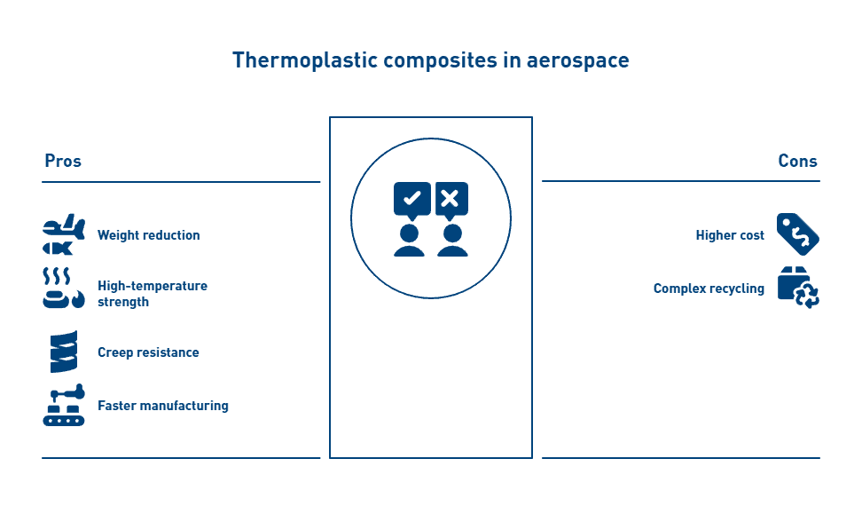
These materials maintain strength at temperatures exceeding 1200°C, essential for jet engine components where creep acceleration occurs. Carbon fiber-reinforced titanium alloys demonstrate exceptional creep resistance at up to 80% of their melting point. Furthermore, manufacturing cycle times can decrease by 80% when using thermoplastics instead of traditional materials.
Semiconductor: Wafer Transport Fixtures Under Thermal Cycling
Semiconductor fabrication equipment requires materials with dimensional stability during thermal cycling. Wafer handling components must exhibit thermal resistance, dimensional stability, and minimal outgassing. Materials used in this sector must withstand exposure to aggressive process chemicals, high temperatures, and vacuums. Polyimide (PI) excels in this environment with superior plasma and temperature resistance compared to industry standard materials. For CMP retaining rings, engineering plastics provide superior properties including high strength, chemical resistance, and dimensional stability.
Industrial: Bearings and Bushings in High-Stress Machinery
Industrial bearings and bushings experience continuous mechanical stress, making creep resistance critical. Composite bearings combining metal and polymer can support static load capacities up to 250 N/mm². PAI demonstrates extremely low thermal expansion and superior creep resistance, making it ideal for tight-tolerance applications such as bearings and bushings. Additionally, ECTFE offers greater strength, abrasion resistance, and creep resistance than softer fluoropolymers like PTFE. For the most demanding applications, Vespel® polyimide maintains its mechanical properties at temperatures up to 260°C (500°F), providing exceptional creep characteristics for valve components where sealing is required.
Conclusion: Selecting the Optimal Creep-Resistant Polymer
Engineers must carefully balance multiple factors when selecting creep-resistant polymers for critical load applications. Above all, understanding the three distinct creep phases, primary, secondary, and tertiary, provides essential insight into predicting long-term material performance. Consequently, materials specialists can design components that maintain dimensional stability throughout their intended service life.
Temperature undoubtedly remains the most significant factor affecting creep behavior. Accordingly, engineers should design for maximum operating temperature rather than average conditions. Additionally, stress duration and load intensity follow non-linear relationships with creep deformation, making accurate load profiling crucial during the selection process.
Material microstructure significantly influences creep resistance. Semi-crystalline polymers generally outperform amorphous variants due to their restricted molecular mobility. Furthermore, higher molecular weight polymers demonstrate superior performance through increased chain entanglements. The addition of reinforcing fillers likewise enhances creep resistance substantially, with glass fiber additions improving stiffness by up to 300%.
Each high-performance polymer offers distinct advantages for specific applications. PEEK excels in high-temperature environments while maintaining excellent mechanical properties. PAI provides exceptional dimensional stability despite thermal cycling. PPS combines chemical resistance with mechanical stability across varying humidity levels. PI demonstrates remarkable thermal stability between -200°C and 400°C. Though PTFE exhibits poor creep resistance, its chemical stability makes it suitable for certain applications when properly reinforced.
Application-specific requirements ultimately dictate material selection. Medical implants benefit from PEEK’s bone-like modulus and radiolucency. Aerospace components require materials that withstand extreme temperatures while minimizing weight. Semiconductor fabrication equipment demands dimensional stability during thermal cycling, making polyimide an excellent choice. Industrial bearings need materials like PAI with low thermal expansion and superior creep resistance.
The proper selection of creep-resistant polymers therefore requires thorough analysis of operating conditions, performance requirements, and material properties. Engineers who carefully evaluate these factors can develop components that maintain dimensional stability and mechanical integrity throughout their service life, even under constant stress at elevated temperatures.
Selecting the appropriate creep resistant polymer demands a thorough understanding of the application’s mechanical, thermal, and environmental requirements. With factors such as load duration, temperature exposure, and material structure significantly influencing long-term performance, engineers must evaluate each variable with precision.
High-performance polymers like PEEK, PAI, PPS, and PI each offer distinct advantages depending on the demands of the operating environment. To ensure optimal performance and dimensional stability under sustained stress, speak with a materials expert to identify the optimal polymer for your critical load application. AIP’s engineering team is available to provide material guidance backed by decades of experience in precision machining and polymer behavior under stress.
FAQs
Q1. Which plastics offer the best creep resistance for critical applications?
High-performance polymers like PEEK, PAI, PPS, and PI demonstrate excellent creep resistance. PEEK, for instance, maintains its structural integrity at high temperatures and offers superior long-term load resistance. PAI provides exceptional dimensional stability, while PPS combines chemical resistance with mechanical stability.
Q2. How does temperature affect the creep behavior of polymers?
Temperature significantly influences creep behavior by altering polymer chain mobility. As temperature increases, polymer chains gain more kinetic energy, allowing them to slide past each other more easily. This can dramatically accelerate creep rates, with studies showing that a temperature increase from 20°C to 80°C can increase creep strain by nearly four times.
Q3. What role does molecular structure play in a polymer’s creep resistance?
The molecular structure of polymers greatly impacts their creep resistance. Semi-crystalline polymers generally exhibit better creep resistance compared to amorphous variants due to their more ordered structure. Additionally, polymers with higher molecular weights tend to have improved creep performance because they form more entanglements between chains, restricting molecular motion.
Q4. How do fillers and reinforcements improve a polymer’s creep resistance?
Incorporating reinforcing fillers can substantially enhance a polymer’s creep resistance. For example, adding just 30% glass fiber can improve creep resistance and increase stiffness by up to 300%. Other fillers like carbon nanotubes or ceramic reinforcements can also limit polymer chain mobility, thereby improving creep resistance.
Q5. What are some industry-specific considerations when selecting creep-resistant plastics?
Different industries have unique requirements for creep-resistant plastics. In medical applications, PEEK is preferred for implants due to its bone-like modulus and radiolucency. Aerospace components require materials that withstand extreme temperatures while minimizing weight. Semiconductor manufacturing needs materials with excellent dimensional stability during thermal cycling, making polyimide a good choice. For industrial bearings and bushings, materials like PAI offer low thermal expansion and superior creep resistance.