What is Thermal Expansion (and Contraction)?
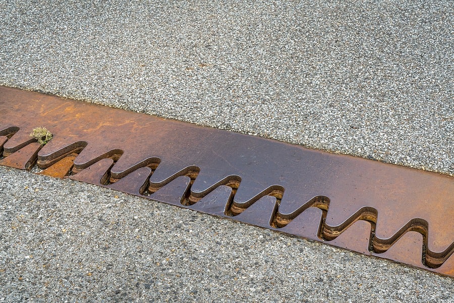 Thermal expansion or contraction occurs when a material is exposed to temperature change and thus leads to change in all dimensions, as well as other physical properties. While this effect is most noticeable in gasses and liquids, it is also notable in solids. Softer materials such as unreinforced polymers experience greater levels of dimensional change per each degree change in temperature.
When it comes to machining polymers, heat is always part of the equation. Increasing the temperature on any polymer or composite can lead to significant changes in dimensions, to part warpage or to internal stress. Therefore, it is crucial for machinists and designers to understand the amount of thermal expansion a material will undergo during machining operations. Ideally, reducing any and all thermal contributors during machining would provide for the least machinist stress during production.
One of the tests that engineers and designers use to measure the dimensional stability of a material under the effects of heat is the coefficient of linear thermal expansion. At AIP, we take great care in providing unrivaled results to ensure the optimal dimensions and properties for machined polymers and composites. Join us in this technical brief as we give an in-depth explanation of the coefficient of linear thermal expansion (CLTE).
The CLTE Equation
The linear coefficient ‘CLTE or α for plastic and polymer materials is calculated as:
a = ΔL / (L0 * ΔT)
Where:
a is coefficient of linear thermal expansion per degree Celsius
ΔL is change in length of test specimen due to heating or to cooling
L0 is the original length of specimen at room temperature
ΔT is temperature change, °C, during test
Calculate a by dividing the linear expansion per unit length by the change in temperature. When reporting the mean coefficient of thermal expansion, the temperature ranges must be specified. It is important to note that with many materials, a can change as temperature changes. It is not always linear, but many times assumed to be linear for most less critical applications or quick estimates.
Recently we were brought in to evaluate a material cracking issue with a Polycarbonate Lens. The cracks were noted around the fastener holes. The fasteners mounted the lens to an aluminum frame. It was discovered that there was basically no or minimal clearance between the fasteners and holes in the Polycarbonate. As the thermal environment deviated over a 100 oF range, the lens obviously expanded and contracted resulting in the fracture. Updating the design to allow for additional clearance solved the problem.
Applications of CLTE
Thermal expansion in materials causes premature cracks and stresses that can lead to part failure. Understanding the CLTE is not only a fiscal concern, but also helpful in determining the type of material for quality and function.
- It is required for design purposes.
- It helps determine dimensional behavior of machined parts subject to temperature changes.
- It also determines thermal stresses that can occur, and cause failure of a solid item composed of different materials when it is exposed to temperature (specially to predict efficient material bonding or while using plastics with metals).
How to Measure CLTE
The most widely used standards to measure coefficient of linear thermal expansion in plastics are ASTM D696, ASTM E831, ASTM E228 and ISO 11359.
Common methods for determining CLTE include:
- Dilatometry
- Interferometry
- Thermomechanical analysis
Dilatometry
With this technique, the specimen is heated in a furnace and displacement of the ends of the specimen are transmitted to a sensor by means of push rod. The push rods may be vitreous silica type, high-purity alumina type, or the isotropic graphite type.
ASTM D696 – This test covers determination of the coefficient of linear thermal expansion for plastic materials having coefficients of expansion greater than 1?µm/(m.°C) by use of a vitreous silica dilatometer. The nature of most plastics and the construction of the dilatometer make -30 to +30°C (-22°F to +86°F) a convenient temperature range for linear thermal expansion measurements of plastics, since most plastics are commonly used within this temperature range.
ASTM E228 – This test is used for temperatures other than -30°C to 30°C to determine linear thermal expansion of solid materials with a push-rod dilatometer.
Interferometry
Using optical interference methods, displacement of the material ends is measured in terms of the number of wavelengths of monochromatic light. While precision is great that with dilatometry, interferometry is not used much above 700 °C (1290 °F).
ASTM E289 – provides a standard method for linear thermal expansion of rigid solids with interferometry that is applicable from –150 to 700 °C (–240 to 1290 °F). It is more applicable to materials having low or negative CLTE in the range of <5 × 10⁻⁶/K (2.8 × 10⁻⁶/°F) or where only limited lengths of thickness of other higher expansion coefficient materials are available.
Thermomechanical Analysis
Measurements are made with a thermomechanical analyzer that has a material holder and probe that transmits changes in length to a transducer. The transducer converts the movements of the probe into an electrical signal.
ASTM E831 (and ISO 11359-2) – These tests are applicable to solid materials that exhibit sufficient rigidity over the test temperature range. It is applicable to the temperature range from −120 to 900°C. The temperature range may be extended depending upon the instrumentation and calibration materials used.
Factors Affecting CLTE Measurements of Plastics
- Fibers and other fillers significantly reduce thermal expansion.
- The magnitude of CLTE increases with rising temperature.
- Molecular orientation also affects the thermal expansion of plastics. The thermal expansion is often affected by the cooling time during processing. This is especially true with semi-crystalline polymers whose crystallization process requires time.
List of CLTE Values for Precision Plastics
| Polymer Name | CLTE Value (10-6 / oC) |
| ABS – Acrylonitrile butadiene styrene | 72-108 |
| PA – Nylon Polyamide, general purpose | 110 |
| PAI – Polyamide-Imides (TORLON) | 3-4 |
| PC – Polycarbonate | 65-70 |
| PE – Polyethylene | 108-200 |
| PEEK – Polyetheretherketone | 4.5-5.5 |
| PEI – Polyetherimide (ULTEM) | 5-6 |
| PP – Polypropylene | 72-90 |
| PS – Polystyrene | 70 |
| PSU – Polysulfone | 55-90 |
| PTFE – Polytetrafluorethylene | 112-135 |
| PVC – Polyvinyl chloride | 54-110 |
| PVDF – Polyvinylidene fluoride (KYNAR) | 128-140 |
As the chart notes, some polymers such as Polyethylene (PE, HDPE, UHMWPE) and Nylon (PA) tend to move more with temperature change. However, polymers like PEEK and TORLON (PAI) have a resistance to heat that rivals those of metals like aluminum (21-24).
Carbon and glass reinforced polymers can result in metal like levels of CLTE. This can be advantageous when mission critical polymer parts are to be mounted to metallic components without an allowance for expansion or contraction.
A chart can give a general idea of the CLTE, but an entire data set with the curve of a material is the best way to determine the right material for your project. Be sure to work with a plastics machining company that can provide you a wide range of data on the CLTE of polymers and composites. Your machinist will be able to identify how temperatures will affect your project’s design and functionality. Talk to one our engineers at AIP about your project design, and we will work with you to provide unrivaled expertise from your project’s initial concept to completion.
Supporting Materials
Certifications and Regulatory Resources
What should you ask your machinist about the material pick for your project?
We’ve got 3 tips on choosing the right material for your design.


