Medical device manufacturing has experienced a significant evolution in recent years, particularly in the area of custom polymer implants and surgical guides. At AIP Precision Machining, we have been at the forefront of this transformation, integrating advanced materials and precision machining techniques that have revolutionized the production of medical implants, prosthetics, and surgical instruments. This progress, driven by our commitment to innovation and quality, has led to enhanced patient outcomes and improved surgical precision, marking a new era in healthcare technology.
The advancements in medical device manufacturing encompass various aspects, from meticulous material selection to rigorous quality control. High-performance polymers like PEEK, expertly machined by our team, have become instrumental in creating biocompatible implants that closely mimic natural tissue properties. Our precision machining techniques ensure the production of intricate medical plastic parts with unparalleled accuracy, reflecting our dedication to excellence.
Additionally, our stringent quality management systems and adherence to FDA regulations guarantee the safety and effectiveness of these implantable devices. This article will explore the cutting-edge processes, materials, and considerations involved in manufacturing custom polymer implants and surgical guides, shedding light on the future of medical device production—a future that AIP Precision Machining is proud to help shape.
Polymer Materials for Custom Implants
Selecting appropriate polymer materials for custom implants is crucial in medical device manufacturing. The choice of material has a significant impact on the implant’s performance, biocompatibility, and regulatory compliance.
Biocompatibility and FDA Regulations
Biocompatibility is essential for materials in contact with bodily fluids and tissues. The FDA regulates medical devices, requiring manufacturers to adhere to strict guidelines. ISO 10993 test results are generally acceptable for applications in the United States, with the testing program depending on factors such as duration of contact with the device.
High-Performance Polymers: PEEK and PAEK
PEEK and PAEK are high-performance polymers widely used in medical implants. PEEK, a semicrystalline thermoplastic, has an elastic modulus close to cortical bone, making it an excellent alternative to titanium. PAEK polymers offer enhanced physical, mechanical, and biological properties, with PEKK showing better elastic modulus and osteointegration compared to PEEK.
Material Selection Criteria
Material selection involves considering factors such as regulatory classification, cost, product characteristics, and sterilization resistance. Functional requirements and necessary material attributes must be identified to eliminate unsuitable materials. Long-term availability and sustainability are also crucial factors in the selection process.
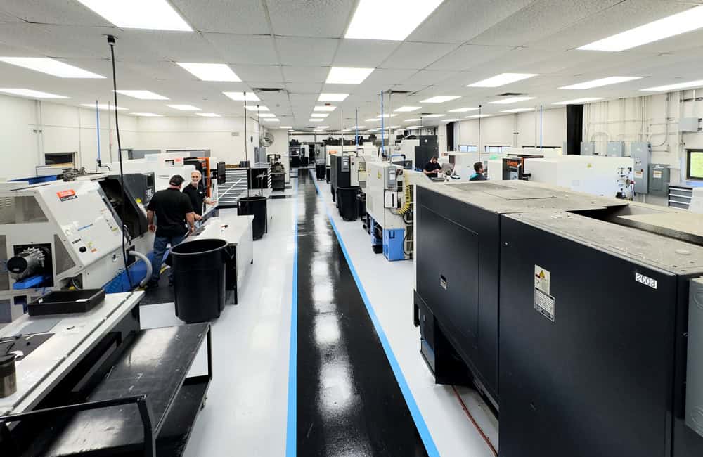
Advanced Manufacturing Techniques
At AIP Precision Machining, we are at the forefront of medical device innovation, combining our expertise in precision machining with the latest in additive manufacturing technology. Our Roboze ARGO 500 enables us to produce complex, high-performance polymer implants and surgical guides with unmatched accuracy and speed. This advanced 3D printing capability, alongside our established CNC machining processes, allows us to deliver customized medical devices that meet the highest industry standards efficiently and precisely.
3D Printing and Additive Manufacturing
3D printing revolutionizes medical device prototyping, enabling rapid development of complex designs. This technique allows for the creation of looks-like, feels-like, and works-like prototypes within hours, using diverse materials to meet specific requirements such as strength and flexibility. It also facilitates the production of custom surgical instruments and patient-specific implants, enhancing surgical precision and outcomes.
CNC Machining for Precision
CNC machining plays a crucial role in medical device manufacturing, particularly for implants and surgical instruments. This computer-controlled process ensures unparalleled precision, achieving tight tolerances of +/- 0.025mm. CNC machining is widely used in producing orthopedic components, dental prostheses, and cardiovascular devices. CNC milling’s versatility allows for the fabrication of intricate parts from various materials, including titanium and medical-grade plastics.
Quality Control and Regulatory Compliance
 In the highly regulated field of medical device manufacturing, rigorous quality control and strict adherence to regulatory standards are essential. Ensuring that every product meets the highest levels of safety, performance, and reliability is a critical responsibility.
FDA Quality System Regulation (QSR)
The FDA’s Quality System Regulation (QSR) establishes a framework for medical device manufacturers to ensure product quality and safety. This regulation requires manufacturers to develop and follow procedures tailored to their specific devices, emphasizing the importance of objective evidence in meeting these requirements. The QSR covers essential elements of a quality system without prescribing specific methods, allowing flexibility for different types of devices and production processes.
ISO 13485 Certification
ISO 13485 is an internationally recognized standard for medical device quality management systems. This certification demonstrates compliance with regulatory requirements and safety standards. It encompasses design, production, installation, and servicing of medical devices. The 2016 version of ISO 13485 places greater emphasis on risk management and risk-based decision-making, reflecting the evolving landscape of medical device manufacturing.
Validation and Verification Processes
Validation and verification are crucial design controls required by the FDA to ensure medical devices are safe, effective, and fit for their intended use. Verification involves checking whether the design meets specified requirements, while validation confirms that the device meets user needs in actual-use conditions. These processes involve various activities, including design reviews, testing, and inspections, and must be documented systematically for FDA review.
Custom Polymer Implants: Design Considerations
The design of custom polymer implants involves several critical factors. Patient-specific modeling and imaging techniques enable precise anatomical matching, improving fit and functionality. Material properties and biomechanics play a crucial role, with polymers offering advantages such as easy manipulation and aesthetic appeal.
However, depending on the application and material, they can also present challenges like inferior mechanical properties and potential adverse reactions. Longevity and wear resistance are essential considerations, as implants must withstand repetitive loading cycles and corrosive environments.
Advanced manufacturing techniques, including 3D printing, have revolutionized the production of patient-specific implants, allowing for more efficient and flexible processes at the point-of-care.
Surgical Guides: Enhancing Precision
Surgical guides play a crucial role in enhancing precision in medical device manufacturing, particularly for implants and guides. These patient-specific instruments are designed to improve accuracy, reduce surgical time, and optimize outcomes. The integration of advanced technologies has revolutionized the production and application of surgical guides.
3D-Printed Cutting and Drilling Guides
3D-printed surgical guides have transformed the landscape of medical procedures. These guides are fabricated using biocompatible materials and are designed to fit precisely on the patient’s anatomy. They assist in bone cutting and implant placement, enabling surgeries with maximum accuracy and minimal invasiveness. The guides are produced using additive manufacturing techniques and can be sterilized using standard autoclave procedures.
Patient-Specific Instrumentation
Patient-specific instrumentation (PSI) utilizes pre-operative imaging to create customized cutting blocks. This technology has shown promise in total knee arthroplasty, where it aims to improve implant alignment and reduce surgical time. PSI guides are designed based on 3D models derived from CT or MRI scans, allowing surgeons to plan resections and implant positioning with precision. While the benefits of PSI are still being evaluated, it has the potential to enhance surgical efficiency and outcomes.
Integration with Computer-Assisted Surgery
The integration of surgical guides with computer-assisted surgery techniques further enhances precision. This combination allows for real-time tracking and adjustment during procedures. Virtual planning software enables surgeons to simulate surgeries beforehand, leading to better comprehension of potential challenges and tailored treatment approaches. The synergy between physical guides and digital planning tools represents a significant advancement in surgical precision and patient-specific care.
Future Trends in Medical Device Manufacturing
The landscape of medical device manufacturing is rapidly evolving, driven by advancements in technology, materials, and processes. As the industry continues to innovate, new trends are emerging that promise to further enhance the precision, customization, and efficiency of medical device production.
Bioactive and Smart Polymers
The future of medical device manufacturing lies in the development of bioactive and smart polymers. These materials respond to environmental changes, mimicking natural biological processes. Thermo-responsive hydrogels, for instance, can form in-situ injectable gels, offering minimally invasive surgical approaches. Self-healing polymers have the capacity to recover after repeated damage, while shape memory polymers can return to their original form. These smart materials are being explored as cell carriers, drug delivery systems, and for use in bioprinting applications.
Nanotechnology in Implant Design
Nanotechnology has opened new avenues for implant surface engineering. By mimicking the nanoscale topography of extracellular matrix components, researchers aim to improve osseointegration and tissue response. Nanopatterned surfaces may enhance fibrin clot adhesion and facilitate osteogenic cell migration. However, the interplay between surface topography and chemistry at the nanoscale requires further investigation to fully understand its potential benefits over micro-scale patterning.
Polymer Selection for Medical Implants
The selection of polymers for medical implants has revolutionized the field of medical device manufacturing. PEEK (polyetheretherketone), a high-performance polymer, has emerged as a leading contender in orthopedic and spinal implants. Its chemical composition imparts resilience, durability, and strength, making it an attractive alternative to traditional metallic materials.
PEEK vs. Traditional Metallic Implants
PEEK offers several advantages over titanium and stainless-steel implants. Its elastic modulus closely matches that of human bone, reducing stress shielding and promoting better load transfer. Unlike metal implants, PEEK is radiolucent, allowing for clearer imaging during post-operative monitoring and reducing radiation exposure for patients. PEEK’s chemical stability ensures long-term stability in the body, minimizing the risk of corrosion and degradation.
Biocompatibility Testing and Standards
Biocompatibility is crucial for implantable materials. PEEK has demonstrated excellent biocompatibility, showing no signs of cytotoxicity, genotoxicity, or immunogenicity. Rigorous testing, including cytocompatibility, genotoxicity, and hemocompatibility assays, ensures the safety of PEEK implants. These tests evaluate cell viability, genetic material damage, and blood interactions, adhering to international standards for biological evaluation of biomaterials.
Customization Potential of Polymers
Polymers offer significant customization potential for medical implants. Their tunable mechanical properties allow for matching the stiffness and strength of native bone. This flexibility enables the creation of patient-specific implants, particularly beneficial in craniofacial and orthopedic applications. Advanced manufacturing techniques, such as 3D printing, further enhance the ability to produce complex, customized implant designs, improving surgical precision and patient outcomes.
Advancements in Polymer Science for Medical Devices
Polymer science has become a cornerstone in the development of cutting-edge medical devices, offering new possibilities for innovation and improved patient care. We at AIP Precision Machining leverage our deep expertise in high-performance polymers to produce medical components that meet or exceed the most stringent industry standards.
This section explores the latest breakthroughs in polymer science, including the development of biocompatible materials with enhanced properties such as increased strength, durability, and flexibility. These advancements are transforming the capabilities of medical devices, enabling the creation of implants and surgical instruments that are more effective, safer, and better suited to the needs of patients.
Novel Polymer Blends and Composites
Polymer-based composites have revolutionized medical device manufacturing, offering enhanced mechanical properties and biological activity. PLLA, a biodegradable polymer, has been combined with bioactive materials to improve osteoregeneration in orthopedic devices. A novel membrane mixing PLLA and tricalcium silicate has shown potential as an antileakage solution for kyphoplasty treatment.
Surface Modifications for Enhanced Integration
Surface modifications of titanium implants have enhanced their biological performance and osseointegration outcomes. Physical modifications at macro, micro, and nano levels improve primary fixation, fibrin matrix formation, and cell growth. Laser ablation generates nano-scale channels, inducing more bone-to-implant contact and creating a biological seal.
Biodegradable and Bioresorbable Polymers
Biodegradable polymers like PGA, PLA, and PLGA are widely employed for bone implants. These materials offer advantages such as tensile strength and non-corrosion properties. However, they experience a loss of mechanical strength over time due to degradation. Ongoing research focuses on optimizing their physicochemical properties for effective therapeutic delivery and tissue engineering applications.
Conclusion
The evolution of medical device manufacturing, particularly in custom polymer implants and surgical guides, has brought about significant improvements in patient care and surgical precision. Advanced materials like PEEK, combined with cutting-edge manufacturing techniques such as CNC machining and 3D printing, have paved the way for more effective and patient-specific medical solutions. This progress has a profound impact on various medical fields, including orthopedics, dentistry, and cardiovascular care, leading to better outcomes and enhanced quality of life for patients.
As the field continues to grow, the focus on precision machining for medical devices and implants remains crucial. The integration of smart polymers, nanotechnology, and bioactive materials promises to further revolutionize the industry, offering new possibilities for personalized healthcare.
To choose the best materials for your medical devices, partner with our team. The ongoing advancements in polymer science and manufacturing techniques are set to shape the future of medical device production, paving the way for more innovative, effective, and patient-centered solutions in healthcare.
Key takeaways
| Section | Key Takeaways |
| Polymer Materials for Custom Implants | This section emphasizes the importance of material selection in medical device manufacturing. High-performance polymers like PEEK and PAEK are featured for their biocompatibility and mechanical properties, making them ideal for implants. The section also discusses material selection criteria, including regulatory compliance, cost, and sterilization resistance. |
| Advanced Manufacturing Techniques | The section details the advanced manufacturing techniques employed by AIP Precision Machining, including 3D printing, CNC machining, and injection molding. These techniques allow for the production of complex and precise medical devices, enabling rapid prototyping and customization while ensuring compliance with FDA standards and other regulatory requirements. |
| Quality Control and Regulatory Compliance | Quality control and regulatory compliance are critical in medical device manufacturing. The section explores the FDA’s Quality System Regulation (QSR) and ISO 13485 certification, highlighting the importance of validation and verification processes to ensure the safety, efficacy, and reliability of medical devices. |
| Custom Polymer Implants: Design Considerations | This section discusses the design considerations for custom polymer implants, including patient-specific modeling, material properties, and biomechanics. It highlights the advantages and challenges of using polymers for implants, such as their flexibility and aesthetic appeal versus their mechanical limitations. |
| Surgical Guides: Enhancing Precision | Surgical guides, particularly those created through 3D printing, are discussed for their role in enhancing surgical precision. The section covers patient-specific instrumentation, integration with computer-assisted surgery, and the benefits of using 3D-printed cutting and drilling guides to improve surgical outcomes and reduce operative time. |
| Future Trends in Medical Device Manufacturing | The future trends in medical device manufacturing are explored, focusing on the development of bioactive and smart polymers, the application of nanotechnology in implant design, and the customization potential of polymers. These advancements are expected to further revolutionize the industry by enhancing the precision and effectiveness of medical devices. |
FAQs
What types of medical devices are constructed from polymers?
Polymers are extensively used in the medical field for various applications. These include the casings and enclosures of medical devices, oxygen concentrators, and compressors, as well as laboratory ware and diagnostic tools. Polymers are also integral in both radiation and non-radiation medical devices, medical packaging, laboratory trays, kits, catheters, tubing, and drug delivery systems.
What are the uses of additive manufacturing in the medical field?
Additive manufacturing (AM), or 3D printing, is utilized in various medical applications. These applications include the creation of implants, prostheses, orthoses, and surgical instruments. AM is also used for developing prototypes and other tools that aid in medical procedures.
Is it possible to 3D print medical implants?
Yes, medical implants can be 3D printed. This technology is particularly useful in reconstructive and plastic surgery for creating patient-specific cranial and maxillofacial implants, as well as bone grafts. These custom implants ensure a perfect anatomical fit, enhance esthetic outcomes, and reduce the likelihood of postoperative infections, thereby also cutting overall treatment costs.


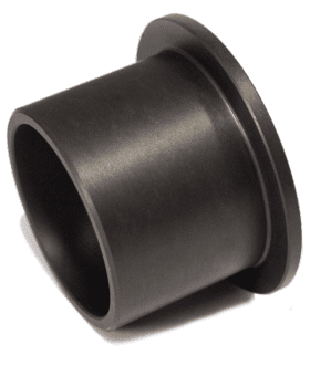 PPS has a low moisture absorption rate and can be machined to the exact tolerances necessary for clearing and shaft. With low-wear, high temperature stability and a low coefficient of friction, the chosen PPS grade proved to be an excellent fit for the log flume’s wheel bushings.