Polyamideimide (PAI) stands as the strongest polymer available today, boasting an exceptional tensile strength of 21,000 psi. When engineers select materials for critical industrial applications, understanding polymer mechanical properties becomes essential for ensuring operational safety and longevity. High-performance polymers like PEEK and Ultem offer impressive tensile strengths of 14,000 psi and 15,200 psi respectively, making them viable alternatives for demanding environments.

The mechanical properties of polymers have gained significant importance as these materials increasingly serve in structural applications, both independently and as matrix materials for composites. Additionally, most polymers exhibit time-dependent mechanical behavior, demonstrated through rate-dependent elastic moduli, yield strength, and post-yield characteristics. This time-dependent nature must be carefully considered when selecting the strongest plastic material for industrial use.

This article examines what truly defines polymer strength in industrial contexts and provides a comprehensive comparison of today’s strongest synthetic polymers. Furthermore, we’ll explore how thermal stability—with materials like PEEK withstanding temperatures up to 260°C and certain polyimide formulations exceeding 300°C—plays a crucial role in material selection for aerospace, automotive, and oil and gas applications.


Defining Strength in Industrial Polymers

Strength in industrial polymers encompasses multiple mechanical properties that determine performance under various loading conditions. Understanding these parameters is essential for selecting materials that can withstand specific industrial demands while maintaining dimensional stability. Engineers must consider several interrelated factors when evaluating polymer strength for critical applications.

Tensile strength vs compressive strength

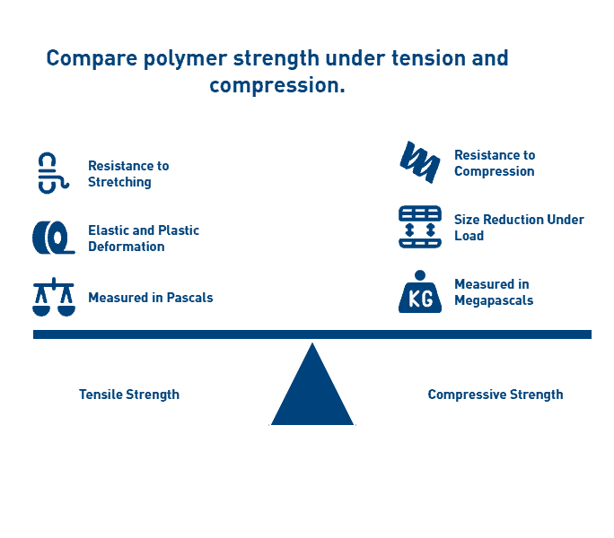
Tensile strength measures a polymer’s ability to resist breaking under tension, calculated as the maximum stress a material can withstand while being stretched before failure. In contrast to tensile forces, compressive strength quantifies a material’s capacity to withstand size reduction when subjected to load without fracturing. This fundamental difference exists because tensile stresses separate polymer atoms, while compressive forces bring them closer together.

When subjected to tensile forces, polymers initially undergo elastic deformation where they return to original dimensions upon stress removal. Subsequently, with increased force, they experience plastic deformation—a permanent, irreversible stretching. Tensile strength is typically expressed in Pascals (Pa), Megapascals (MPa), or pounds per square inch (psi).

Compressive strength values often differ significantly from tensile measurements for the same polymer. For instance, polyamide-imide exhibits compressive yield strength of 130 MPa, while polyimide reinforced with glass fiber reaches 220 MPa. These differences highlight why material selection must account for the primary stress type encountered in the application.
The mathematical relationship between stress and cross-sectional area is expressed as: σ = F/A where σ represents stress, F is the applied force, and A is the cross-sectional area. This equation applies to both tensile and compressive scenarios, though the direction of force differs.

Creep resistance and modulus explained

Creep resistance represents a critical property for industrial polymers used in structural applications, especially those subjected to constant loads at elevated temperatures. Creep is defined as the time-dependent deformation that occurs when a solid material is subjected to constant stress below its yield strength. For polymers especially, this phenomenon results from their inherent viscoelastic nature.

The creep process typically progresses through three distinct stages:

  1. Primary creep (Stage I): Characterized by decreasing creep rate as resistance to deformation increases
  2. Secondary creep (Stage II): Exhibits relatively constant creep rate and determines the time to failure
  3. Tertiary creep (Stage III): Shows accelerating deformation due to internal fracturing, leading to failure

Temperature significantly influences creep behavior in polymers. As temperature increases, chain mobility accelerates, resulting in greater creep deformation. One study observed that increasing temperature from 20°C to 50°C caused creep strain to increase 2.15 times, while at 80°C, the increase factor reached 3.93.

Material composition also affects creep resistance. Semi-crystalline polymers generally demonstrate better creep resistance than amorphous polymers because crystalline regions restrict molecular movement. Consequently, polymers with higher crystallinity percentages often exhibit superior dimensional stability under sustained loads.

Young’s modulus (elastic modulus) represents another critical strength parameter, defined as the ratio of stress to strain within a material’s proportional limit. Essentially, it measures a polymer’s stiffness—higher values indicate greater resistance to deformation under load. Modulus values for industrial polymers typically range from 0.7 GPa for HDPE to 12 GPa for glass-fiber reinforced polyimide.

How polymer stress-strain curves are interpreted

Stress-strain curves provide comprehensive insights into polymer mechanical behavior under applied forces. These graphs plot stress (force per unit area) against strain (extension per unit length) as a polymer undergoes deformation. For engineers, these curves reveal crucial information about elastic modulus, yield strength, ultimate tensile strength, and failure characteristics.

A typical polymer stress-strain curve exhibits several distinct regions:

  1. Linear elastic region: The initial straight-line portion where stress and strain are proportional according to Hooke’s Law. The slope of this line defines the Young’s modulus of elasticity.
  2. Yield point: Where the curve deviates from linearity, indicating the transition from elastic to plastic deformation. This represents the stress level at which permanent deformation begins.
  3. Strain hardening region: Beyond the yield point, where plastic deformation continues but requires increasing stress due to molecular realignment.
  4. Ultimate tensile strength: The maximum stress value on the curve, after which necking (localized narrowing) may occur.
  5. Fracture point: Where complete material failure occurs.

Different polymer types produce characteristically different curve shapes. Glassy or semi-crystalline polymers below their glass transition temperature typically show higher modulus values but limited elongation before failure. In contrast, elastomers or semi-crystalline polymers above their glass transition temperature demonstrate lower initial modulus but much greater elongation capacity.

The stress-strain relationship for polymers exhibits significant time and temperature dependence, distinguishing their behavior from other material classes. This viscoelastic nature explains why polymer performance under short-duration testing may not accurately predict long-term behavior under sustained loads—further emphasizing the importance of creep testing for industrial applications.


PEEK: A High-Performance Polymer for Harsh Environments

Polyetheretherketone (PEEK) ranks among the most capable engineering thermoplastics available, defined by its remarkable mechanical stability in extreme environments. Unlike standard polymers, PEEK maintains its structural integrity under conditions that would rapidly degrade conventional materials.

PEEK polymer structure and semi-crystalline behavior

PEEK derives its exceptional properties from its unique molecular architecture—a rigid aromatic backbone composed of repeated units featuring one ketone bond and two ether bonds in an aromatic ring. This chemical structure creates inherent stiffness at the molecular level, contributing to its impressive thermal and mechanical performance.

As a semi-crystalline thermoplastic, PEEK contains both ordered crystalline regions and disordered amorphous zones. The crystalline domains provide strength and chemical resistance, whereas the amorphous regions contribute to toughness and flexibility. Processing conditions significantly influence the final crystallinity level, which can reach up to 48% maximum achievable crystallinity. Higher crystallinity typically results in greater strength and chemical resistance at the expense of some impact resistance.

The semi-crystalline nature gives PEEK excellent wear resistance, dimensional stability, and fatigue resistance—properties that remain largely intact even at elevated temperatures. Moreover, PEEK’s crystalline structure contributes significantly to its exceptional creep resistance, allowing it to withstand sustained loads without permanent deformation.

Tensile strength: 14,000 psi

PEEK exhibits impressive tensile strength of 14,000 psi (90-100 MPa) in its unfilled form, positioning it among the strongest thermoplastic polymers commercially available. This strength level allows PEEK components to replace metal parts in numerous applications while providing substantial weight reduction.

The material demonstrates an elastic modulus of 3.6 GPa, indicating excellent stiffness under load. Indeed, PEEK’s mechanical profile extends beyond mere tensile strength—its flexural strength reaches approximately 25,000 psi (165 MPa), providing exceptional resistance to bending forces.

For applications requiring even greater mechanical performance, carbon fiber-reinforced PEEK grades can achieve tensile strengths of 29,000 psi while maintaining properties at temperatures as high as 299°C. These enhanced formulations offer strength-to-weight ratios that outperform many metals and alloys.

Thermal resistance up to 480ºF

PEEK’s exceptional thermal stability sets it apart from most engineering polymers. The material features a glass transition temperature of approximately 143°C (289°F) and melts around 343°C (649°F). In practical applications, PEEK maintains its mechanical properties at continuous operating temperatures up to 480°F (250°C).

In fact, PEEK can function in steam or high-pressure water environments for thousands of hours at temperatures of 480°F with no significant degradation of properties. This remarkable thermal resilience results from the strong chemical bonds in its aromatic backbone structure.

The material’s thermal durability is complemented by excellent flame resistance. PEEK achieves a UL94 V-0 flammability rating, indicating it resists combustion up to nearly 600°C and produces minimal smoke or toxic emissions when exposed to flame.

Applications in aerospace and oil & gas

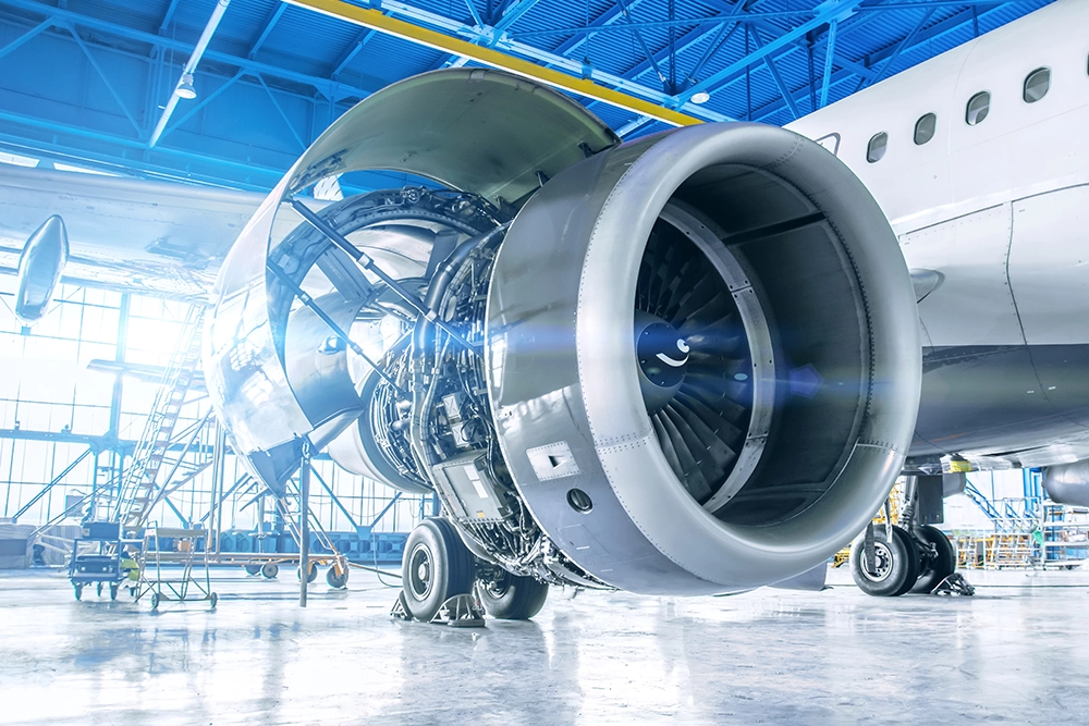
In aerospace applications, PEEK’s combination of light weight, high strength, and temperature resistance makes it ideal for replacing metal components. The material finds use in structural brackets, interior components, and applications where weight reduction and flame resistance are critical. As one aerospace industry application highlights, “PEEK polymer has been specified for aircraft landing gear hubcaps withstanding impacts of flying debris and has excellent environmental resistance in harsh conditions”.

Within the oil and gas industry, PEEK excels in extreme downhole environments where temperatures, pressures, and chemical exposure would destroy conventional materials. Applications include:

  • Sealing systems and face seals at wellheads containing high-pressure production fluids and gasses
  • Bearing components that benefit from PEEK’s self-lubricating properties
  • Valve plates, rings, piston rings, and rod packing in reciprocating compressors
  • Labyrinth seals and downhole electrical connectors

PEEK’s combination of properties—including chemical resistance to sour gas environments, excellent wear characteristics, and thermal stability—makes it particularly valuable in these demanding applications. Its ability to maintain structural integrity while resisting corrosion offers significant advantages over traditional metal components in hostile oil field environments.


Torlon (PAI): The Strongest Unfilled Thermoplastic

Torlon (polyamide-imide) stands in a class of its own among engineering thermoplastics, transitioning from thermoplastic to thermoset during post-processing. First and foremost, this unique chemical transformation gives Torlon exceptional mechanical properties that surpass virtually all other melt-processable polymers, making it the material of choice for the most demanding industrial applications.

Tensile strength: 21,000 psi

Torlon PAI boasts the highest tensile strength of any unreinforced thermoplastic at 21,000 psi, establishing it as the strongest polymer available for industrial applications. This exceptional strength results from its molecular structure and the post-curing process that increases molecular weight through chain extension. Alongside impressive tensile properties, Torlon demonstrates remarkable compressive strength exceeding 35,000 psi, far surpassing most engineering plastics.

Notably, Torlon retains its mechanical integrity at extreme temperatures, maintaining functional properties at continuous operating temperatures up to 500°F (260°C). Its heat deflection temperature significantly exceeds that of PEEK, allowing Torlon to retain higher strength and stiffness at elevated temperatures. Despite these high-temperature capabilities, Torlon performs admirably in cryogenic conditions without becoming brittle, offering truly versatile performance across temperature extremes.

The post-curing process dramatically transforms Torlon’s properties, increasing elongation from approximately 5% to 15%. This significant improvement in toughness occurs without sacrificing strength, yielding a material that combines rigidity with impact resistance.

Excellent wear and radiation resistance

Torlon exhibits superior tribological properties that make it exceptionally suitable for wear applications. In particular, wear-resistant grades offer excellent performance under both high velocity and high pressure conditions, often eliminating the need for lubrication. As a result, Torlon excels in applications requiring:

  • Bearings and seal rings in harsh environments
  • Valve seats and piston rings in high-performance engines
  • Precision gears for aerospace applications
  • Compressor components in oil and gas equipment

PAI polymers demonstrate outstanding radiation resistance, significantly outperforming many other engineering plastics when exposed to high levels of radiation. This property proves invaluable for components in nuclear power installations and space applications. Yet another advantage is Torlon’s exceptional chemical resistance to strong acids, most organic compounds, and aviation and automotive fluids, allowing it to function reliably in chemically aggressive environments.

Limitations: brittleness and cost

Nevertheless, Torlon has several limitations that engineers must consider. The material absorbs moisture, which can affect dimensional stability in applications lacking proper humidity control[152]. This moisture absorption becomes particularly concerning for precision components with tight tolerances.

Although post-curing improves toughness, fully cured Torlon cannot be recycled, presenting both economic and environmental challenges. In addition to recycling limitations, Torlon exhibits sensitivity to thermal shock when subjected to sudden high-temperature exposures.

Overall, Torlon typically commands a higher price than other high-performance polymers like PEEK[152]. This cost premium results from its specialized manufacturing processes and unique material properties. Despite the higher investment, many engineers find the cost justified for mission-critical components where performance at temperature extremes and under mechanical stress is essential.

Torlon’s distinctive combination of strength, temperature resistance, and wear properties continues to make it invaluable for applications where other polymers would fail, particularly in aerospace, automotive transmissions, and oil and gas equipment[173] where reliability under extreme conditions is paramount.


Vespel (Polyimide): Superior Creep and Wear Resistance

Vespel stands out among high-performance polymers as a premier polyimide material, renowned for its unmatched combination of thermal stability and mechanical strength in extreme environments. Since its introduction in 1965, this remarkable polymer has established itself as the material of choice for applications where other polymers reach their operational limits.

High-temperature stability beyond 300ºC

Vespel delivers exceptional thermal performance, maintaining structural integrity at temperatures ranging from cryogenic conditions to over 300°C (570°F). For short-term exposure, certain grades can withstand temperatures up to 400°C, with potential to handle up to 538°C (1,000°F) in inert environments. This extraordinary thermal stability stems from Vespel’s unique polyimide molecular structure, which features imide linkages providing dimensional stability even under extreme heat.

Comparatively, Vespel exhibits the lowest coefficient of thermal expansion among unfilled plastics, making it ideal for precision components that must maintain tight tolerances across wide temperature fluctuations. This property, coupled with its outstanding creep characteristics, enables parts machined from Vespel to maintain dimensional stability under sustained loads at elevated temperatures.

Low coefficient of friction in dry environments

Vespel specifically excels in tribological applications, offering self-lubricating properties that eliminate the maintenance requirements typically associated with metal components. Different grades provide varying levels of friction performance:

  • SP-1: The original unfilled grade offering superior wear resistance and insulation properties
  • SP-3: Formulated for vacuum and dry environments with remarkably low outgassing
  • SP-21: Graphite-enhanced grade with improved low-friction properties, functioning effectively with or without lubrication
  • SP-211: Features a lower coefficient of friction than SP-21, incorporating PTFE to further reduce friction even in unlubricated conditions

Vespel’s ductility simultaneously contributes to its excellent sealing capabilities, primarily valuable in valve components where sealing against high-pressure fluids is critical. The polymer’s combination of low friction and exceptional wear resistance results in components that operate reliably for extended periods without lubrication, a significant advantage in environments where lubricants would degrade or contaminate processes.

Ideal for aerospace and semiconductor use

Aerospace engineers have embraced Vespel for its unique performance characteristics in critical applications. The material serves admirably in components such as locking elements for fasteners, valve seats and seals, thermal isolators, bearings, bushings, and splines. Its lightweight construction compared to metals offers substantial weight savings without compromising performance.

In semiconductor manufacturing, Vespel’s high purity and minimal outgassing properties prove invaluable. The SP-3 grade, furthermore, demonstrates superior performance in vacuum environments where contamination must be strictly controlled. The material’s electrical insulation properties coupled with its dimensional stability make it ideal for chip test sockets, wafer clamping rings, and high-temperature substrate handling.

Vespel’s exceptional creep and stress relaxation behavior outperforms virtually all other polymers, enabling it to maintain sealing force in high-pressure applications over extended periods. This characteristic, along with its ability to operate in extreme temperature environments, positions Vespel as an indispensable material for industries where failure is not an option.


Ultem (PEI): Balanced Strength and Machinability

Ultem (polyetherimide or PEI) represents an optimal balance between mechanical performance and processing capability, making it a versatile choice for demanding industrial applications. As an amorphous thermoplastic, Ultem offers a unique combination of properties that position it strategically between standard engineering plastics and ultra-high-performance polymers like PEEK and Torlon.

Tensile strength: 15,200 psi

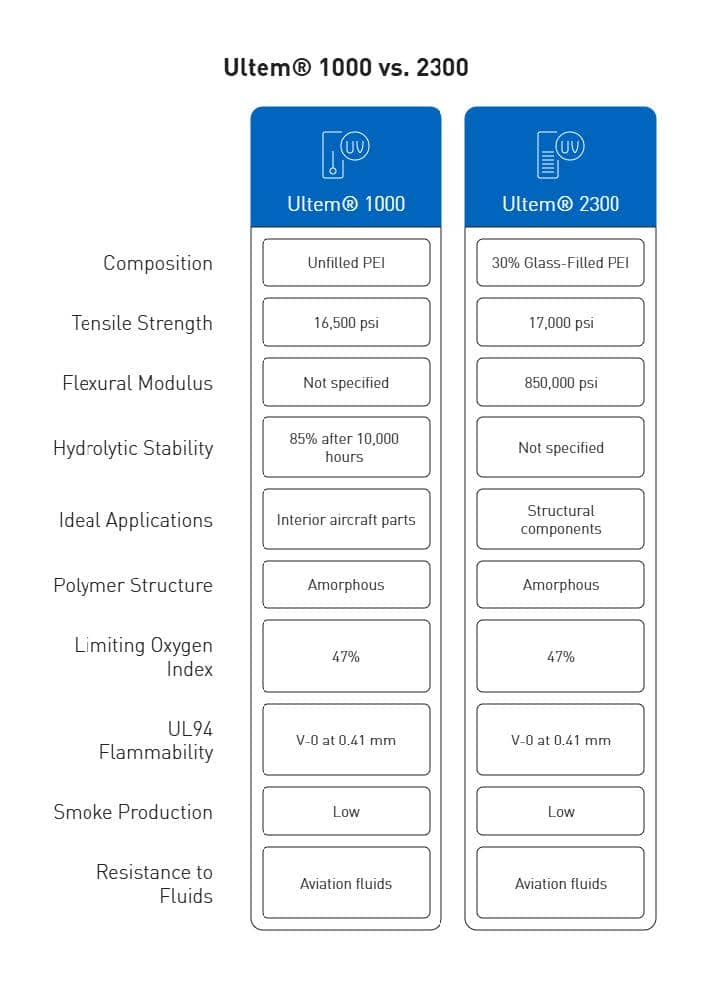
Ultem demonstrates impressive mechanical integrity with a tensile strength of 15,200 psi (105 MPa) in its unfilled grade. This strength level exceeds many standard engineering thermoplastics while providing excellent dimensional stability under load. The material’s mechanical profile extends beyond tensile properties, featuring flexural strength of 20,000 psi and compressive strength reaching 22,000 psi in unfilled grades.

For applications requiring enhanced structural performance, glass-fiber reinforced variants offer substantially improved properties. The Ultem 2000 series includes formulations with various glass fiber contents:

  • Ultem 2100 (10% glass): 16,800 psi tensile strength
  • Ultem 2200 (20% glass): 16,900 psi tensile strength
  • Ultem 2300 (30% glass): 17,000 psi tensile strength

Correspondingly, these reinforced grades exhibit markedly improved flexural strength up to 27,000 psi and compressive strength reaching 32,000 psi. The glass reinforcement primarily enhances rigidity and dimensional stability while maintaining many beneficial characteristics of the base polymer.

High dielectric strength and chemical resistance

Historically, Ultem has been recognized for possessing the highest dielectric strength of any commercially available thermoplastic, measured at 830 V/mil according to ASTM D149. This exceptional electrical insulation capability makes Ultem particularly valuable for circuit boards, high-temperature lighting, electrical connectors, and electronic housings.

Regarding chemical stability, Ultem excels in hot water and steam environments—a distinguishing characteristic among high-performance polymers. The material retains 100% of its tensile strength after 2,000 steam autoclave cycles at 270°F and maintains 85% of tensile strength even after 10,000 hours of immersion in boiling water. Forthwith, this extraordinary hydrolysis resistance makes Ultem suitable for medical devices requiring repeated sterilization and food processing equipment exposed to high-temperature cleaning protocols.

Ultem’s chemical resistance extends to acids, oils, fats, and alcohols, along with exceptional flame resistance without requiring additives. It achieves a UL94 V-0 flammability rating and exhibits a high limiting oxygen index (LOI) of 47%, generating minimal smoke during combustion.

Cost-effective alternative to PEEK

While PEEK offers slightly superior thermal resistance and chemical stability, Ultem provides an economical alternative at approximately one-third the cost. This substantial price difference makes Ultem attractive for applications where PEEK’s extreme properties exceed requirements.

From a processing perspective, Ultem demonstrates excellent machinability compared to PEEK. The material allows for more efficient machining under similar conditions due to its slightly lower strength and reduced tool wear. This processing advantage translates to lower manufacturing costs for precision components while still delivering exceptional performance characteristics.

Ultem’s balanced property profile makes it suitable for diverse applications including aircraft interior components (meeting FAA regulation 25.853 for flammability), medical devices requiring sterilization, automotive electrical systems, and semiconductor manufacturing equipment. For precision machined components requiring tight tolerances, Ultem offers predictable dimensional stability across wide temperature ranges, making it ideal for high-precision industrial parts.


PPS: Chemically Resistant and Thermally Stable

Polyphenylene sulfide (PPS) occupies a strategic position among high-performance polymers, offering an exceptional balance of thermal stability, chemical resistance, and mechanical strength at a moderate price point. With its aromatic rings linked by sulfur atoms, PPS delivers performance capabilities that make it suitable for demanding industrial applications where both chemical exposure and elevated temperatures are concerns.

Tensile strength: 12,500 psi

PPS exhibits impressive tensile strength of 12,500 psi (86 MPa) in its standard formulation, positioning it as the fourth strongest high-performance thermoplastic in unfilled form. For applications requiring enhanced mechanical properties, glass-fiber-reinforced variants achieve tensile strengths up to 17,500 psi, significantly expanding its performance envelope. The material’s compressive strength reaches approximately 21,500 PSI according to ASTM D695 testing, making it suitable for load-bearing components in industrial settings.

Beyond pure strength values, PPS demonstrates excellent rigidity and creep resistance under sustained loads, maintaining its mechanical integrity even at elevated temperatures. This characteristic makes it ideal for precision components that must retain their dimensions under mechanical stress. Among its mechanical attributes, PPS offers:

  • High modulus and exceptional creep resistance
  • Outstanding stress cracking resistance
  • Excellent abrasion resistance and wear properties

These mechanical properties remain largely intact across PPS’s broad operating temperature range, contributing to its reliability in structurally demanding applications.

Excellent dimensional stability and flame retardance

PPS maintains dimensional stability under conditions that would cause significant deformation in conventional polymers. The material exhibits remarkable thermal properties with a melting temperature of 280°C (540°F) and continuous service capability up to 200°C (392°F) with short-term resistance to temperatures as high as 260°C (500°F).

Equally important, PPS demonstrates minimal water absorption below 0.1%, allowing it to maintain dimensional precision across humidity fluctuations—a critical factor for components with tight tolerances. This combination of thermal stability and low moisture absorption results in exceptional dimensional consistency in variable environmental conditions.

Among high-performance polymers, PPS stands out for its inherent flame retardancy. The material achieves UL94 V-0 flammability ratings without requiring additional flame retardant additives. Its molecular structure causes it to merely char during combustion rather than sustain a flame, enhancing safety in applications where fire resistance is critical.

Used in automotive and electrical components

Within the automotive sector, PPS has become invaluable for components exposed to high temperatures, chemicals, and mechanical stress. Primary applications include:

  • Engine components including valve covers and thrust washers
  • Fuel system components owing to resistance to all common automotive fuels
  • Brake system parts requiring thermal stability
  • Under-hood electrical connectors and housings

The electrical and electronics industry similarly benefits from PPS’s unique property profile. Its high dielectric strength coupled with thermal stability makes it ideal for:

  • Electrical connectors and switches requiring reliability in harsh conditions
  • Circuit boards for high-temperature applications
  • Insulators and components for semiconductor manufacturing
  • Electronic housings requiring both flame retardance and dimensional stability

PPS offers manufacturers a valuable alternative to more expensive high-performance polymers like PEEK for applications operating at moderate temperatures. Its exceptional hydrolytic stability—including resistance to hot water, steam, and high-pressure fluids—further expands its utility across diverse industrial settings.


Comparative Analysis of Top 5 Strongest Polymers

When evaluating the top five strongest polymers side by side, critical performance metrics reveal distinct advantages for specific applications. Engineers must carefully weigh these differences when selecting materials for high-stress industrial environments.

Strength-to-weight ratio comparison

The strength-to-weight ratio (specific strength) offers a critical metric for applications where weight reduction provides substantial benefits. Among high-performance polymers, this property varies considerably:
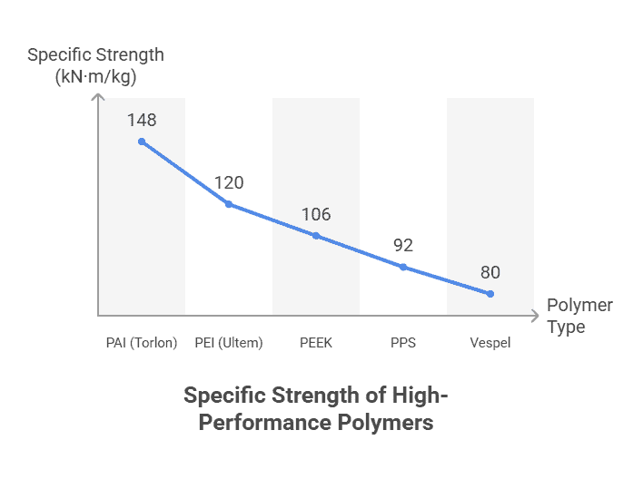
  • PAI (Torlon): With tensile strength of 21,000 psi and density of 1.42 g/cm³, PAI offers the highest specific strength at approximately 148 kN·m/kg
  • PEI (Ultem): Provides 15,200 psi strength with 1.27 g/cm³ density, yielding approximately 120 kN·m/kg
  • PEEK: Delivers 14,000 psi strength with 1.32 g/cm³ density, resulting in approximately 106 kN·m/kg[371]
  • PPS: Exhibits 12,500 psi strength with 1.36 g/cm³ density, providing approximately 92 kN·m/kg
  • Vespel: Despite excellent thermal properties, its specific strength ranks slightly lower among these top five

Primarily, these strength-to-weight ratios exceed those of conventional polymers by factors of 3-5, making them suitable replacements for metal components in weight-critical applications.

Thermal and chemical resistance matrix

Chemical resistance varies substantially across these polymers, with environmental conditions dramatically affecting performance:

PEEK withstands continuous temperatures up to 260°C while maintaining excellent resistance to acids, bases, and hydrocarbons. Alternatively, Vespel operates reliably beyond 300°C—the highest among these materials—yet costs significantly more.

Hydrolytic stability demonstrates another critical difference; Ultem retains 85% of its tensile strength after 10,000 hours in boiling water, outperforming PEEK in this specific measure. Effectively, PPS offers the best overall chemical resistance, particularly against acids and bases, even surpassing PEEK in certain environments.

Maximize Performance with Engineered Polymers – Talk to an AIP expert about selecting and machining the strongest polymer for your demanding environment.

Creep resistance in polymers under load

Creep resistance—the ability to maintain dimensional stability under sustained load—represents a decisive factor for precision components. Temperature substantially impacts this property, with creep strain increasing by factors of 2.15-3.93 as temperatures rise from 20°C to 80°C.

Among these materials, Vespel demonstrates “outstanding creep resistance”, maintaining mechanical properties at continuous temperatures up to 500°F. Likewise, PAI exhibits “superior creep resistance”, making it particularly valuable for tight-tolerance applications.

The molecular structure fundamentally determines creep behavior—polymers with higher crystallinity (like PEEK and PPS) typically outperform amorphous polymers in creep resistance. Higher cross-linking density, typically found in PAI after post-curing, correspondingly enhances long-term dimensional stability under load.


Machinability and Precision Part Considerations

CNC machining delivers precision components for mission-critical applications where high-performance polymers must withstand extreme pressures and stresses. Manufacturing these components involves careful consideration of material properties, machining parameters, and tolerance requirements.

High-pressure plastic components and tolerances

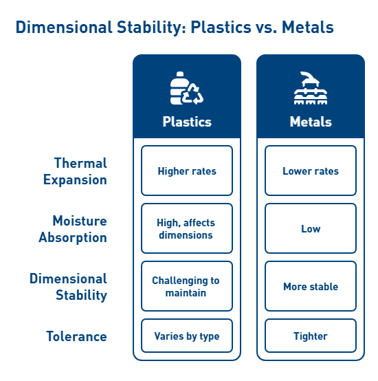
Manufacturing precision plastic parts demands strict adherence to tolerance specifications. Modern aerospace, medical, and defense applications frequently require components with tolerances as precise as ±0.001 inches. Primarily, the material choice significantly impacts achievable tolerances. Materials with low melt points present greater dimensional control challenges.

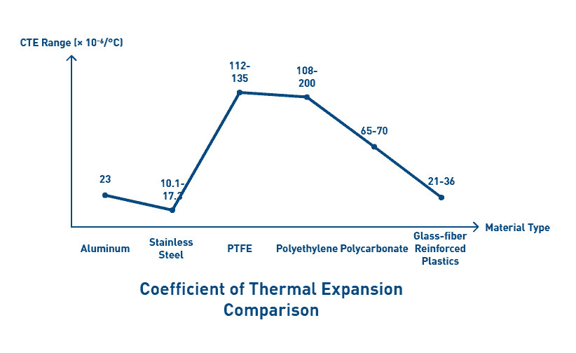
Temperature fluctuations critically affect dimensional stability due to polymer’s high coefficient of thermal expansion (CTE). For instance, UHMW has a CTE of 0.0001 inch/degree, meaning a 10-foot piece can move 0.012 inches with just one degree temperature change. Henceforth, material selection must account for both operational conditions and manufacturing environment.

Machinable polymers for tight tolerances

Among high-performance polymers, achievable tolerances vary considerably:

  • Acetal: ±0.001 inches
  • PEEK: ±0.001 inches
  • Nylon: ±0.002 inches
  • PVC: ±0.002 inches
  • UHMW/HDPE: ±0.005 inches

For optimal machining results, cutting parameters must be carefully controlled. Feed rates typically fall between 0.005 and 0.015 IPR, depending on material and cutting method. To circumvent heat buildup at the cutting interface, manufacturers employ sharp tools, moderate feeds, and high chip evacuation rates.

Fixturing techniques prove equally important. Since polymers are more elastic than metals, they become susceptible to deformation under excessive clamping pressure. In this case, customized fixtures providing support without excessive force yield better results.

How AIP Precision Machining supports material selection

With over 37 years of experience working with professionals across medical sciences, aerospace, defense, and specialized industrial sectors, AIP assists clients in navigating crucial material selection factors including:

  • Electrical properties and dielectric requirements
  • Mechanical strength and wear resistance
  • Chemical exposure considerations
  • Thermal stability requirements
  • Industry-specific standards and regulations

In order to deliver optimal machined products, AIP employs state-of-the-art technology and maintains high quality standards throughout the manufacturing process, consistently achieving tight tolerances of ±0.001 inches or better.


Conclusion: Strategic Selection of High-Performance Polymers

Selecting the optimal polymer for demanding industrial applications requires thorough analysis of multiple performance factors beyond simple strength measurements. Throughout this examination of high-performance polymers, PAI (Torlon) clearly emerges as the strongest available option with its remarkable 21,000 psi tensile strength. Nevertheless, material selection decisions must consider application-specific requirements rather than relying solely on strength values.

Each polymer discussed offers distinct advantages for particular environments. PEEK delivers exceptional chemical resistance and thermal stability up to 260°C, making it suitable for harsh chemical settings. Vespel stands out with superior creep resistance and thermal performance beyond 300°C, though at higher cost. Ultem provides an economical alternative with balanced properties and excellent dielectric strength. PPS offers outstanding chemical resistance with inherent flame retardancy at a moderate price point.

Engineers must consequently evaluate several critical factors when selecting materials:

  • Mechanical requirements (tensile strength, compressive strength, modulus)
  • Thermal stability needs (maximum continuous operating temperature)
  • Chemical exposure conditions
  • Creep resistance under sustained loads
  • Dimensional stability requirements
  • Cost constraints

Undoubtedly, the strength-to-weight ratio becomes particularly significant when weight reduction provides substantial benefits. PAI offers the highest specific strength at approximately 148 kN·m/kg, followed by PEI at 120 kN·m/kg and PEEK at 106 kN·m/kg. These values exceed conventional polymers by factors of 3-5, making them viable replacements for metal components in weight-critical applications.

Temperature significantly influences polymer performance, especially regarding creep behavior. As temperatures rise from 20°C to 80°C, creep strain increases dramatically, underscoring the importance of evaluating materials under actual operating conditions rather than relying solely on room-temperature data.

The manufacturing process additionally plays a crucial role in component performance. Precision machining capabilities must match the selected material’s properties to achieve required tolerances. Materials with higher dimensional stability generally allow for tighter tolerances during manufacturing.

Most importantly, engineers should approach polymer selection as a multi-dimensional decision process, considering the complete performance profile rather than focusing exclusively on strength values. This comprehensive approach ensures optimal material selection for critical industrial applications where failure is not an option.

For engineers tasked with selecting the strongest polymer for high-pressure, high-stress environments, working with a precision machining partner is essential. AIP Precision Machining brings over 40 years of specialized experience in high-performance thermoplastics, providing expert guidance in material selection and delivering components that meet the most demanding tolerance and performance requirements. Contact AIP today to discuss your application needs and ensure optimal performance through expertly machined polymer solutions.


FAQs

Q1. What is the strongest polymer available for industrial applications?

Polyamide-imide (PAI), also known as Torlon, is currently the strongest polymer available for industrial use. It has an exceptional tensile strength of 21,000 psi, making it ideal for demanding applications where high strength is critical.

Q2. How does PEEK compare to other high-performance polymers?

PEEK offers an excellent balance of properties, including high tensile strength (14,000 psi), thermal stability up to 480°F, and chemical resistance. While not as strong as PAI, PEEK outperforms many other polymers and is widely used in aerospace and oil & gas industries.

Q3. What are the key factors to consider when selecting a polymer for industrial use?

When selecting a polymer, consider mechanical properties (strength, stiffness), thermal stability, chemical resistance, creep behavior, dimensional stability, and cost. The specific requirements of your application should guide the selection process.

Q4. Which polymer offers the best combination of strength and cost-effectiveness?

Ultem (PEI) offers a good balance of strength (15,200 psi tensile strength) and cost-effectiveness. It’s often considered a more economical alternative to PEEK for applications that don’t require extreme temperature or chemical resistance.

Q5. How do high-performance polymers compare to metals in terms of strength-to-weight ratio?

High-performance polymers like PAI, PEI, and PEEK offer strength-to-weight ratios that exceed conventional materials by 3-5 times. This makes them excellent alternatives to metals in weight-critical applications, particularly in aerospace and automotive industries.
Follow AIP Precision Machining on Linkedin

linkedin logo

Fireman wearing fire protection suite and oxygen tank exercise hold hose spray water near fire truck

Flame retardant plastics are becoming increasingly vital to aerospace engineering. These specialized materials provide critical fire safety protection in environments where even a small fire can have catastrophic consequences. The difference between achieving a V-0 rating and a V-2 rating under UL 94 standards can determine whether a component proceeds to production or requires costly redesign.

For aerospace applications, flame retardant plastics serve multiple essential functions. They protect sensitive equipment as protective coverings and line cargo holds, fuel storage tanks, engine compartments, and electrical control rooms where fire hazards are present. However, selecting the appropriate material presents significant challenges for engineers. UL 94 ratings are thickness dependent, meaning a resin that passes safety standards at 1.5mm might fail at 0.74mm. Additionally, specialized formulations like polyamide PA 2210 FR have been specifically developed to meet the stringent flammability, smoke, and toxicity standards for civil aerospace, typically qualifying for “flying hardware” with wall thicknesses down to 2mm.

This guide examines the regulatory landscape, material selection criteria, and testing protocols aerospace engineers must navigate when specifying flame retardant plastics. Because these materials improve fire safety but can complicate product end-of-life handling, engineers must balance performance requirements with sustainability considerations. From inherently flame retardant options to additive-based solutions, this article provides a comprehensive framework for making informed material decisions that meet both regulatory requirements and performance needs.


Regulatory Landscape for Aerospace Flame Retardant Plastics

The regulatory framework governing flame retardant plastics in aerospace applications presents a complex landscape that engineers must navigate with precision. Unlike consumer applications, aerospace materials face stringent scrutiny due to the catastrophic consequences of fire events at altitude.

FAA FAR 25.853 and EASA CS-25 Requirements

Federal Aviation Regulation (FAR) 25.853 establishes comprehensive flammability requirements for materials used in aircraft interiors. This standard mandates that materials must self-extinguish rapidly to limit fire spread and produce minimal smoke to reduce visibility and respiratory hazards. The European equivalent, EASA CS-25.853, contains essentially identical requirements, creating a harmonized global standard. Furthermore, China’s Civil Aviation Administration (CAAC) utilizes CCAR 25.853, which mirrors these specifications.

The regulations categorize materials based on their application within the aircraft. For interior ceiling panels, wall panels, and partitions, materials must pass a 60-second vertical burn test where the average burn length cannot exceed 15 cm (6 inches) and the average flame time after removal of the flame source cannot exceed 15 seconds. Meanwhile, floor coverings, textiles, and seat cushions face slightly different criteria with a 12-second vertical burn test where burn length cannot exceed 20 cm (8 inches).

Notably, these requirements vary by aircraft compartment. The Federal Aviation Administration (FAA) introduced Amendments 25-59, 29-23, and 121-184 to require that transport category aircraft be equipped with seat cushions providing enhanced fire resistance, with compliance mandatory after November 26, 1987.

UL 94 vs ASTM E162 and E662

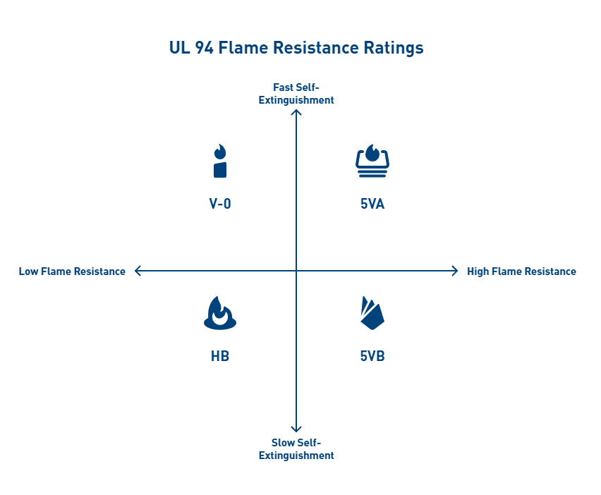
While aerospace-specific standards take precedence, Underwriters Laboratories (UL) 94 testing provides a preliminary indication of a plastic’s flammability characteristics. UL 94 contains multiple test methods: 94HB (Horizontal Burn), 94V (Vertical Burn), 94VTM (thin materials), 94-5V (enclosures), 94HBF/HF (foams), and Radiant Panel.

The classifications range from 5VA (most flame retardant) to HB (least flame retardant). For instance, V-0 rated materials must stop burning within 10 seconds after flame application with no flaming drips allowed, whereas V-2 materials can burn up to 60 seconds and permit flaming drips.

In contrast, ASTM E162 (Radiant Panel Test) measures surface flammability using a radiant heat source. This small-scale test determines a flame spread index and is often required for mass transit and railway applications. ASTM E662, conversely, quantifies smoke density by measuring light attenuation in a closed chamber under both flaming and non-flaming conditions.

Material Compliance Documentation for Aerospace and Defense

Documentation serves as the cornerstone of regulatory compliance in aerospace applications. Each material must have associated test reports demonstrating adherence to relevant standards. Primarily, compliance with FAR/CS 25.853 must be maintained throughout the aircraft’s operational life, including after cabin upgrades or refurbishments.

For material approval, a Supplemental Type Certificate is not necessary; instead, a letter of FAA engineering approval is considered adequate. However, all documentation must be properly archived and readily traceable to each material or part number in use.

During certification, it’s essential to note that each set of specimens must pass weight loss and burn length criteria independently. For example, in accordance with Part 25, Appendix F—Part II, paragraph (a)(4), burn length may not exceed 17 inches on at least two of the specimen sets.

Engineers selecting flame retardant plastics for aerospace applications must thoroughly understand these regulatory requirements and ensure proper documentation throughout the material’s lifecycle to avoid costly compliance issues later.


Material Selection Criteria Based on Application Zones

Selecting appropriate flame retardant plastics for aerospace applications requires engineers to consider specific performance requirements based on where components will be installed. Different zones within an aircraft present unique challenges that demand tailored material solutions.

Cabin Interiors: Low Smoke and Toxicity Requirements

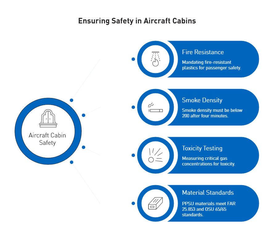
The aircraft cabin environment demands materials that prioritize passenger safety during fire events. Following the late 1980s FAA statistics showing approximately 40% of survivors from impact-related crashes died from post-crash fire and smoke exposure, stringent regulations were implemented in 1987 mandating fire-resistant plastics in all passenger planes.

Cabin interior materials must meet comprehensive Fire, Smoke, and Toxicity (FST) requirements. Smoke density tests require values below 200 after burning for four minutes. Equally important, toxicity testing measures concentrations of critical gasses including:

  • Carbon monoxide (CO)
  • Hydrogen cyanide (HCN)
  • Hydrogen fluoride (HF)
  • Hydrogen chloride (HCl)
  • Sulfur dioxide (SO2)
  • Nitrogen oxides (NOx)

Polyphenylsulfone (PPSU) materials like Solvay’s RADEL® have become industry standards for cabin applications, offering exceptional toughness alongside meeting FAR 25.853 requirements. These materials deliver better impact resistance and chemical stability than other sulfone-based polymers while meeting the OSU 65/65 heat release standards.

Engine Compartments: High Heat and Chemical Resistance

Engine compartment applications present substantially different challenges than cabin interiors, primarily requiring exceptional thermal stability alongside flame retardance. Materials in these zones must withstand continuous operating temperatures above 200°C while maintaining structural integrity.

Polyphenylene sulfide (PPS) stands out for engine compartment applications with its melting point exceeding 280°C and heat distortion temperature above 260°C. Moreover, this material offers long-term use capability between 220-240°C. PPS degrades very slowly at high temperatures, remaining stable for extended periods in air at 200°C, and maintaining 40% of its weight even in inert gas at 100°C.

Besides heat resistance, PPS provides inherent flame retardance without additional additives, achieving UL94 V-0 classification. This self-extinguishing property prevents fire propagation in critical engine zones where fuel and ignition sources coexist.

Electrical Housings: Dielectric Strength and Flame Retardance

Electrical components present unique demands, requiring materials that combine electrical insulation properties with flame retardance. The ideal insulation for higher voltage aerospace systems must be lightweight, chemically stable, and provide good corona suppression while withstanding high voltages.

Dielectric strength—the maximum voltage an insulating material can withstand before breakdown—is expressed as voltage per unit thickness (volts/mil). This property becomes crucial in aerospace applications where high voltage systems operate in confined spaces with minimal insulation thickness.

Wire and cable insulation throughout the aircraft commonly uses thermosetting resins and thermoplastics. For general applications inside the pressure shell, high-performance wire jacketing typically includes radiation cross-linked poly(ethylene-tetrafluoroethylene) (ETFE) and composite constructions with poly(tetrafluoroethylene) (PTFE). In higher temperature and fuel areas, PTFE sees almost exclusive use, while filled PTFE provides superior burn-through resistance for the most demanding applications.

Electrical housings must also maintain their dielectric properties after extended environmental exposure. This requirement makes material selection particularly challenging, as engineers must balance electrical performance with mechanical properties and flame retardance across a wide temperature range.


Overview of Inherently Flame Retardant and Additive-Based Plastics

Aerospace engineers must navigate two primary categories of flame retardant plastics: those with inherent flame resistance and those requiring additives to achieve suitable fire protection. Each approach presents distinct advantages and limitations for critical aerospace applications.

Inherently Flame Retardant Plastics: PEI, PSU, PEEK

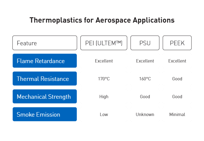
High-performance thermoplastics with built-in flame resistance offer significant advantages in aerospace applications. Polyetherimide (PEI), commonly known as ULTEM™, stands out with its exceptional thermal properties and inherent flame retardance. PEI achieves UL 94V-0 and 5VA flammability ratings without requiring any flame retardant additives. With a continuous service temperature of 170°C coupled with high mechanical strength, PEI has become a preferred material for aircraft interiors due to its low smoke emission characteristics.

Polysulfone (PSU) shares many characteristics with PEI, though with slightly lower thermal resistance (160°C versus 170°C). Nevertheless, PSU still offers excellent flame retardance for less thermally demanding applications.

PEEK (polyetheretherketone) similarly performs well under fire conditions while producing minimal smoke density among comparable materials. This inherent flame resistance makes these polymers particularly valuable for applications where additive-free solutions are preferred.

Flame Retardant Additives for Plastics: Brominated vs Halogen-Free

When inherently flame-resistant polymers aren’t suitable, engineers turn to additive approaches. These additives function through distinct mechanisms:

  • Vapor phase inhibition: Halogenated additives disrupt combustion at the molecular level
  • Solid phase char-formation: Creates an insulating carbonaceous layer
  • Quench and cool: Releases water molecules that cool the polymer

Brominated flame retardants (BFRs) represent approximately 30% of global flame retardant production by volume. Though effective at relatively low concentrations, these additives face increasing scrutiny due to environmental persistence.

Consequently, phosphorus-based alternatives have gained prominence. Organophosphorus flame retardants account for roughly 20% of global production. Modern phosphinate-based solutions like Exolit™ OP provide high flame retardancy while maintaining mechanical properties throughout the product lifecycle.

Trade-offs Between Additive Load and Mechanical Properties

The relationship between additive concentration and mechanical performance presents critical engineering trade-offs. Most polymers require approximately 20% minimum filler content to show appreciable flame retardancy improvement, with typical loadings of 50-60%. Unfortunately, such high concentrations often compromise mechanical integrity.

This relationship isn’t always straightforward, though. In certain formulations, additives like tetrabromobisphenol A (TBBPA) at 10-20% concentration actually improved compressive strength by 22-29% while simultaneously enhancing flame retardance. Similarly, TBBPA increased abrasion resistance by over 200% in some composites.

For aerospace applications where mechanical requirements are stringent, engineers must carefully balance flame retardance with structural integrity. Halogen-free intumescent formulations often require higher loading than their halogenated counterparts to achieve equivalent performance, thereby presenting greater mechanical property challenges.


Testing Protocols and Certification Pathways

The certification process for flame retardant plastics in aerospace requires rigorous testing protocols that validate material performance under controlled fire conditions. Successful navigation through these pathways demands thorough understanding of test configurations and their relationship to real-world applications.

Vertical and Horizontal Burn Test Configurations

Vertical burn testing represents the cornerstone of aerospace flammability certification. According to FAA requirements, specimens must be rectangular (minimum 3 by 12 inches or 75 by 305 mm) and mounted vertically in a draft-free cabinet. The 60-second vertical test mandates that materials self-extinguish within 15 seconds after flame removal, with average burn length not exceeding 6 inches (152 mm). In contrast, the 12-second vertical test allows a slightly longer 8-inch (203 mm) maximum burn length.

Horizontal burn testing evaluates materials’ flame spread characteristics when oriented horizontally—an arrangement that better simulates certain in-service conditions. This test applies a standardized flame for 15 seconds to one edge of the specimen. Materials pass if their burn rate remains below specified thresholds: 2.5 inches/minute for FAR 25.853(b-2) or 4 inches/minute for FAR 25.853(b-3).

Thickness-Specific Certification Challenges

Material thickness significantly impacts flame retardance performance and certification outcomes. As the factual data indicates, a resin passing at 0.059 inches (1.5mm) may fail entirely at 0.029 inches (0.74mm). This thickness dependence creates substantial challenges for aerospace engineers designing thin-walled components.

UL 94 classifications clearly demonstrate this thickness-performance relationship:

  • Parts ≥3.0mm thick can achieve 5VA ratings (highest protection)
  • Parts ≥1.5mm thick may qualify for 5VB ratings
  • Parts ≥0.75mm typically achieve V-0 ratings
  • Parts ≥0.4mm often limited to V-2 ratings

Role of Third-Party Labs and Material Suppliers

Independent laboratories provide critical verification services throughout the certification process. These facilities maintain specialized equipment including draft-free test cabinets, calibrated burners, and precise measurement tools. Many labs maintain active approvals from major aerospace manufacturers like Boeing and Airbus.

Material suppliers likewise play an essential role by providing UL Yellow Cards—certifications confirming materials have undergone comprehensive safety testing. These documents specify exact formulations and applicable thickness ranges, serving as crucial reference points during material selection.

Given testing variability between facilities, engineers should carefully consider laboratory credentials, especially since small differences in test execution can significantly impact results. Throughout certification, close collaboration between engineers, testing laboratories, and material suppliers remains essential for navigating the complexities of flame retardant certification.

Sustainability and Environmental Considerations

Environmental and health concerns surrounding traditional flame retardants are reshaping material selection criteria for aerospace applications. As regulatory landscapes evolve, engineers must consider sustainability alongside performance metrics.

PFAS in Flame Retardant Additives: Regulatory Trends

The regulatory environment for per- and polyfluoroalkyl substances (PFAS) has tightened significantly. In April 2024, the EPA designated PFOA and PFOS as hazardous substances under the Comprehensive Environmental Response, Compensation, and Liability Act. Subsequently, regulators established maximum concentration levels at 4 parts per trillion for PFOA and PFOS, and 10 ppt for PFHxS, PFNA, and GenX Chemicals.

Despite these restrictions, the aerospace industry remains highly dependent on PFAS for critical applications. Currently, many proposed exemptions for transport applications exist, yet these remain insufficient for comprehensive aerospace needs. Industry experts estimate complete PFAS replacement could take decades.

Recyclability of Flame Retardant Thermoplastics

Flame retardant materials present significant recycling challenges. Thermoplastics treated with flame retardants typically undergo only thermal recycling, as chemical separation proves difficult. Thereafter, identifying and separating different thermoplastic types becomes problematic, as each material has unique chemistry and recycling prospects.

Promising developments include mono-material approaches using polyurethane resin. Unlike conventional epoxy resins, PUR enables chemical recycling through solvolysis, recovering both the polyol fraction and carbon fibers from CFRP components. Second-life applications for recycled aerospace thermoplastics include warehouse trays, conveyor systems, and outdoor equipment housings.

Non-Halogenated Alternatives and Green Certifications

Non-halogenated flame retardants have emerged as environmentally preferable alternatives. Phosphorus-based systems, generally non-toxic and effective at char formation, have established an environmentally friendly profile. Presently, mineral-based additives are gaining traction as “green” solutions.

Bio-based flame retardants derived from lignin, starch, chitosan, and phosphorus compounds effectively reduce heat release and smoke emission. For aerospace applications specifically, products like Melapur flame retardants offer halogen-free solutions without antimony or heavy metals.

Major suppliers including Clariant have developed phosphinate-based technologies like Exolit OP that maintain performance properties throughout product lifecycle and after recycling. First, these solutions provide high flame retardancy; second, they maintain mechanical strength; third, they offer proven recyclability. This transition toward sustainability aligns with broader industry efforts to balance fire safety with environmental responsibility.


Conclusion

Aerospace engineers face multifaceted challenges when selecting flame retardant plastics for critical applications. Throughout this guide, we explored how regulatory frameworks fundamentally shape material selection decisions. FAA FAR 25.853, EASA CS-25, and UL 94 standards establish clear performance thresholds that materials must meet before consideration for aerospace applications. These requirements vary significantly based on installation location, from cabin interiors demanding low smoke and toxicity to engine compartments requiring exceptional thermal stability.

Material selection accordingly requires careful evaluation of application-specific needs. Cabin components demand materials like polyphenylsulfone (PPSU) that meet stringent FST requirements, while engine compartments benefit from polyphenylene sulfide (PPS) with its superior heat resistance. Electrical housings, meanwhile, need materials balancing dielectric strength with flame retardance properties.

The dichotomy between inherently flame retardant polymers and additive-based solutions presents another critical decision point. High-performance thermoplastics such as PEI, PSU, and PEEK offer built-in flame resistance without additives, albeit at higher material costs. Conversely, additive-based approaches provide more flexibility but often necessitate trade-offs between flame retardance and mechanical properties.

Testing protocols further complicate material selection. Engineers must recognize that vertical and horizontal burn tests yield different results, while material thickness significantly impacts certification outcomes. Close collaboration with third-party laboratories and material suppliers therefore becomes essential for navigating these complexities.

Sustainability considerations undoubtedly influence modern material selection decisions. Regulatory trends restricting PFAS usage, coupled with growing emphasis on recyclability, push engineers toward non-halogenated alternatives and bio-based flame retardants. Though environmental regulations continue evolving, aerospace applications still require exemptions due to their uniquely demanding performance requirements.

Effective flame retardant plastic selection ultimately requires balancing multiple competing factors: performance requirements, regulatory compliance, weight constraints, cost considerations, and environmental impact. Engineers must evaluate these factors systematically rather than focusing solely on fire performance. This comprehensive approach ensures selected materials not only meet immediate certification requirements but also remain viable throughout the aircraft’s operational lifespan despite evolving regulations and environmental standards.


FAQs

Q1. What are the key regulatory standards for flame retardant plastics in aerospace?

The main standards are FAA FAR 25.853 and EASA CS-25, which set requirements for flammability, smoke emission, and toxicity. UL 94 ratings are also commonly used to classify flame retardant performance.

Q2. How do material requirements differ for various aircraft zones?

Cabin interiors need materials with low smoke and toxicity. Engine compartments require high heat and chemical resistance. Electrical housings must balance dielectric strength with flame retardance.

Q3. What are the advantages of inherently flame retardant plastics?

Inherently flame retardant plastics like PEI, PSU, and PEEK offer built-in fire resistance without additives. This can result in better overall performance and fewer environmental concerns compared to additive-based solutions.

Q4. How does material thickness affect flame retardant certification?

Material thickness significantly impacts flame retardance performance. A plastic that passes certification at one thickness may fail at a lower thickness, creating challenges for designing thin-walled components.

Q5. What sustainability trends are impacting flame retardant plastic selection?

There’s a growing shift towards non-halogenated and bio-based flame retardants due to environmental concerns. Recyclability is also becoming more important, though it remains challenging for many flame retardant materials.

Follow AIP Precision Machining on Linkedin

linkedin logo

medical machined components

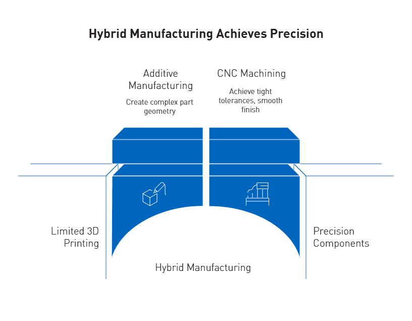
Hybrid manufacturing technology reduces total production costs by 35% and shortens complex parts processing cycles by 50% compared to traditional methods. This revolutionary approach combines 3D printing (additive manufacturing) and CNC machining (subtractive manufacturing) to create superior medical machined components with unmatched precision and efficiency. The integration of these complementary technologies addresses the limitations of each individual method while maximizing their respective strengths.

When creating precision medical components, manufacturers face significant challenges with traditional production methods. CNC machining alone delivers exceptional accuracy but struggles with complex internal geometries and is more labor-intensive. On the other hand, 3D printing offers remarkable flexibility for design alterations without additional equipment setup. By combining additive and subtractive processes, medical device CNC machining achieves the best of both worlds—the design freedom of 3D printing with the precision finishing of multi-axis machining. Additionally, this hybrid approach optimizes surface quality from Ra30μm in selective laser melting to Ra0.4μm, meeting the stringent requirements for medical device implantation.

Precision machining ensures accuracy and consistency in crafting intricate medical components, allowing for the production of complex parts that meet the high standards required in the medical industry. Furthermore, advanced materials used in precision machining enhance the durability and reliability of these critical medical components. This combination of technologies represents the future of medical parts machining, offering unprecedented design possibilities while maintaining the exacting tolerances essential for patient safety.


How CNC and 3D Printing Work Together in Medical Machining

The synergy between additive and subtractive manufacturing creates a powerful methodology for producing precision medical components. This collaborative approach enables manufacturers to create intricate internal structures with 3D printing before achieving precise shapes and surface finishes through CNC machining.

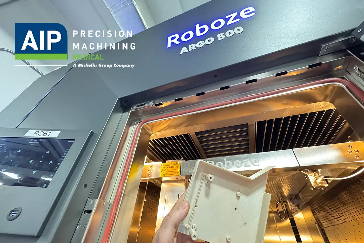
Near-Net Shaping with Roboze ARGO 500

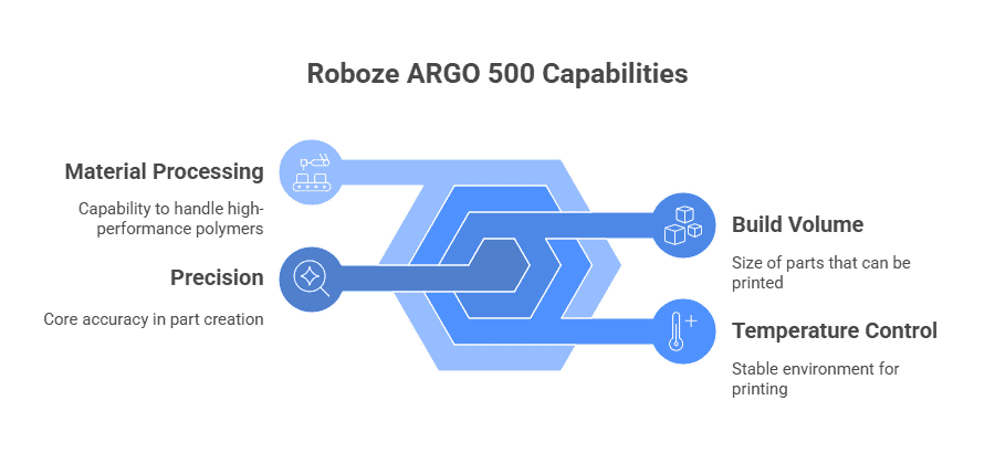
The Roboze ARGO 500 represents a significant advancement in medical component manufacturing. This industrial-grade 3D printer creates near-net shaped parts with 10μm positioning precision in the XY axis and handling build volumes up to 500x500x500 mm.

The system’s patented beltless technology ensures low surface roughness and CNC-grade accuracy while requiring minimal maintenance. Operating with extrusion temperatures reaching 500°C, it effectively processes high-performance polymers essential for medical applications. The system’s controlled environment maintains chamber temperatures up to 180°C, enabling stable prints with built-in annealing characteristics.

Precision Finishing with Multi-Axis CNC

Following the additive process, multi-axis CNC machining transforms the near-net shaped components into finished medical products. This subtractive technique enhances dimensional accuracy and surface quality – critical factors for medical device functionality. The process effectively takes 3D-printed parts with relatively rough surface finishes (Ra30μm) and refines them to medical-grade smoothness (Ra0.4μm). Multi-axis CNC machining particularly excels at creating precise geometries, tight tolerances, and sterilization-compatible surfaces necessary for implantable devices and surgical instruments.

Post-Processing for Sterilization-Ready Surfaces

Post-processing represents the final critical stage in hybrid medical manufacturing. Throughout this phase, components undergo precision cleaning and finishing operations specifically designed for medical-grade requirements. Proper post-processing ensures medical components can withstand rigorous sterilization protocols without degradation. The hybrid approach enables manufacturers to optimize surface characteristics for both functional performance and biocompatibility.

This integrated methodology significantly improves production efficiency, with studies showing hybrid manufacturing can reduce costs by 4-9% compared to conventional methods. Moreover, the approach creates excellent structures for osseointegration in implantable components. By combining these complementary technologies, manufacturers achieve superior results impossible with either technology alone.


Why Hybrid Manufacturing Outperforms Traditional Methods

Medical device manufacturers are consistently seeking manufacturing methods that offer distinct advantages over conventional approaches. The convergence of CNC machining and 3D printing in hybrid manufacturing delivers several key benefits for precision medical components.

Design Flexibility for Complex Geometry Medical Components

Hybrid manufacturing excels in creating intricate medical geometries that would be impossible or cost-prohibitive using traditional methods alone. This process allows for internal channels, lattice structures, and organic shapes that are essential in medical applications. Unlike conventional methods, hybrid approaches enable designers to build components with complex internal features first through additive manufacturing, consequently refining external surfaces with CNC machining. This dual capability is particularly valuable for customized prosthetics and implants where internal structures affect both weight and functionality.

Speed to Market with Agile Prototyping

The agile methodology inherent in hybrid manufacturing drastically reduces development cycles for medical devices. Working prototypes are produced frequently throughout development, enabling early verification through unit tests and iterative manual validation.

This approach allows manufacturers to identify and tackle critical design aspects first, hence reducing product risk. Medical device companies utilizing agile development report faster regulatory approval pathways since designs can be quickly modified based on stakeholder feedback without restarting the entire process.

Cost Efficiency in Low-Volume Production

For medical components typically produced in smaller quantities, hybrid manufacturing presents compelling financial advantages:

  • Elimination of expensive tooling costs required in traditional manufacturing
  • Reduced inventory carrying costs through on-demand production
  • Lower overall production costs—between 4-9% compared to conventional methods

Enhanced Mechanical Properties in Super Polymers

Super polymers processed through hybrid manufacturing maintain exceptional performance characteristics even in extreme conditions. Materials like PEEK demonstrate remarkable thermal versatility, functioning across wide temperature ranges while retaining structural stability. In fact, when properly processed through hybrid methods, these components can achieve tensile strength approximately 71.6% of injection-molded equivalents. This combination of strength, biocompatibility, and radiolucence makes hybrid-manufactured components ideal for applications where both mechanical properties and patient monitoring are crucial.


Material Considerations for Medical Hybrid Manufacturing

Selecting appropriate materials remains a critical factor in successful hybrid manufacturing for medical applications. The unique combination of additive and subtractive processes demands materials that maintain integrity throughout both production stages.

PEEK and PPSU: Biocompatibility and Sterilization Compatibility

PEEK (Polyetheretherketone) stands out as an exceptional polymer for medical applications, offering biocompatibility for implants with ISO 10993 certification and a modulus similar to human cortical bone. This material demonstrates remarkable sterilization resistance, withstanding over 1,500 steam autoclave cycles without significant property degradation. PPSU (Polyphenylsulfone) surpasses other sulfone-based polymers with impact resistance measuring up to 13 ft-lbs/in. Radel PPSU maintains its properties after 1,000 autoclave cycles, making it ideal for reusable medical instruments.

Torlon Medical Applications for High-Load Environments

Torlon PAI (Polyamideimide) delivers unmatched performance among melt-processable thermoplastics. Its compressive strength doubles that of PEEK when unfilled. Torlon’s exceptional wear resistance ensures longevity in peristaltic pump rollers and prosthetic bushings. Medical grade Torlon offers high modulus, radiolucency, sterilization compatibility, and superior dimensional stability across its entire service temperature range.

Machining Radiolucent and Implantable Polymers

Implantable medical devices require biocompatible materials that serve functions for 30+ days. PEEK’s radiolucent properties allow unobstructed imaging through MRI, X-rays, and CT scans. Carbon fiber reinforcement can boost structural strength for load-bearing applications. Additionally, barium sulfate additives increase radiopacity for surgical monitoring without affecting biocompatibility.

Contamination Control in Polymer-Only Machining Environments

Dedicated polymer-only machining environments essentially eliminate metallic cross-contamination risks. Medical components require strict adherence to ISO 13485 and FDA standards for quality management. Ensuring sterilization begins with selecting manufacturers committed to preventing contamination at even sub-molecular levels.


AIP Precision Machining: Certified Excellence in Medical Manufacturing

For three decades, AIP Precision Machining has established itself as a leader in producing advanced medical machined components. Their commitment to quality extends throughout their entire manufacturing process, from initial concept through final delivery.

ISO 13485 and FDA-Registered Facility Standards

AIP operates under ISO 13485:2016 compliance and maintains FDA registration status, having successfully passed audits from the most demanding orthopedic and medical device OEMs. These certifications reflect their adherence to the international standard specifically designed for medical device quality management systems. This regulatory framework ensures consistent quality, proper documentation, and risk-based decision making throughout the manufacturing process.

±0.002 mm Tolerance Capabilities

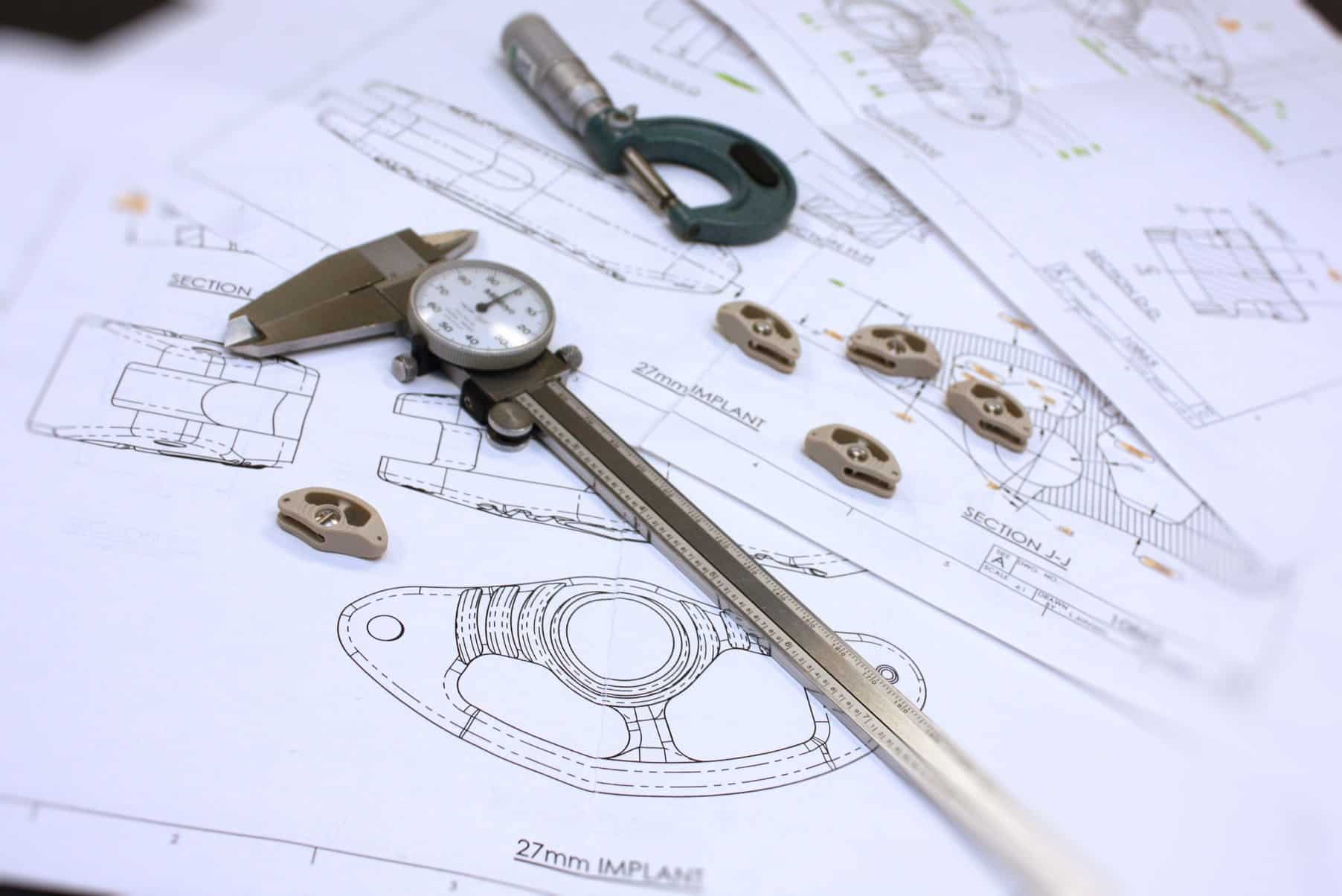
Precision defines AIP’s manufacturing approach, with tolerance capabilities reaching ±0.002 mm. This exceptional accuracy allows their team to machine custom medical components within ten-thousandths of an inch or less. Such precision is crucial for components like surgical instruments, implantable prototypes, and diagnostic equipment where micron-level tolerances are mandatory rather than optional.

Dedicated Polymer-Only Machining Environment

AIP exclusively machines plastics, thereby eliminating the risk of metallic cross-contamination. This dedicated approach proves especially valuable for biocompatible applications where material purity directly impacts patient safety. Their specialized environment maintains strict hygienic procedures throughout the manufacturing process.

Roboze ARGO 500 for High-Performance Additive Manufacturing

The integration of Roboze ARGO 500 technology into AIP’s capabilities elevates their hybrid manufacturing potential. This system delivers 10μm positioning precision in XY axis, creating large-format parts with industrial-grade accuracy and exceptional dimensional repeatability. The system’s beltless technology ensures CNC-grade precision throughout the additive process.

Schedule a Design-for-Manufacturing Consultation – Partner with our engineering team at AIP to optimize your part for both additive and CNC production.


Conclusion

The future of medical component manufacturing clearly belongs to hybrid manufacturing technologies. This integrated approach effectively addresses the limitations of traditional methods while delivering unprecedented precision and efficiency. Companies accordingly benefit from 35% lower production costs and 50% shorter processing cycles, particularly essential for time-sensitive medical innovations.

Medical devices demand exacting standards that hybrid manufacturing consistently meets through its complementary processes. CNC machining brings ±0.002 mm tolerance capabilities, while additive technologies create previously impossible internal geometries. Together, these technologies transform surface quality from Ra30μm to medical-grade Ra0.4μm finishes.

Super polymers processed through this hybrid methodology maintain exceptional performance characteristics across challenging medical environments. PEEK demonstrates remarkable biocompatibility with ISO 10993 certification, while PPSU withstands 1,000 autoclave cycles without degradation. Torlon PAI similarly excels with compressive strength doubling that of PEEK, making these materials ideal for demanding medical applications.

AIP Precision Machining stands at the forefront of this manufacturing revolution with three decades of specialized experience. Their ISO 13485:2016 compliance and FDA registration guarantee adherence to stringent quality management systems. The dedicated polymer-only environment eliminates cross-contamination risks, thus ensuring patient safety remains paramount throughout production.

The combination of Roboze ARGO 500 technology and multi-axis CNC capabilities provides medical device manufacturers unprecedented design freedom. This approach especially benefits complex geometries, customized implants, and specialized surgical instruments that traditional manufacturing methods struggle to produce efficiently.

Medical component development teams should therefore consider partnering with AIP for their next project. Their expertise spans the entire production process from initial design consultation through final quality verification. Schedule a design-for-manufacturing consultation today to discover how hybrid manufacturing technologies can optimize your medical components for both performance and production efficiency.


Key Takeaways

Hybrid manufacturing combining CNC machining and 3D printing is revolutionizing medical component production, delivering superior results that neither technology can achieve alone.

  • Hybrid manufacturing reduces costs by 35% and shortens processing cycles by 50% compared to traditional methods while achieving medical-grade surface finishes.
  • Complex internal geometries become possible through 3D printing’s design freedom, followed by CNC machining’s precision finishing for tight tolerances.
  • Super polymers like PEEK and PPSU maintain exceptional biocompatibility and can withstand over 1,000 sterilization cycles without degradation.
  • Dedicated polymer-only machining environments eliminate metallic contamination risks while maintaining ISO 13485 and FDA compliance standards.
  • Tolerance capabilities reach ±0.002 mm precision with surface quality improvements from Ra30μm to Ra0.4μm for implantable medical devices.

This manufacturing approach particularly excels in low-volume medical device production, enabling rapid prototyping and customized implants while meeting the stringent quality requirements essential for patient safety and regulatory approval.


FAQs

Q1. How does hybrid manufacturing combine CNC machining and 3D printing for medical components?

Hybrid manufacturing integrates 3D printing for creating complex internal geometries and near-net shapes, followed by CNC machining for precision finishing. This combination allows for intricate designs with tight tolerances and medical-grade surface finishes, achieving results impossible with either technology alone.

Q2. What are the key advantages of hybrid manufacturing over traditional methods for medical devices?

Hybrid manufacturing offers several benefits: 35% lower production costs, 50% shorter processing cycles, greater design flexibility for complex geometries, faster prototyping, and cost-efficiency in low-volume production. It also allows for enhanced mechanical properties in super polymers used for medical applications.

Q3. Which materials are commonly used in hybrid manufacturing for medical components?

Common materials include PEEK and PPSU for their biocompatibility and sterilization resistance, Torlon PAI for high-load environments, and various radiolucent and implantable polymers. These materials maintain their integrity throughout both additive and subtractive manufacturing processes.

Q4. How does hybrid manufacturing improve surface quality for medical components?

Hybrid manufacturing can significantly improve surface quality, transforming 3D-printed parts with relatively rough surface finishes (Ra30μm) to medical-grade smoothness (Ra0.4μm) through precision CNC machining. This level of surface refinement is crucial for implantable devices and surgical instruments.

Q5. What certifications are important for manufacturers using hybrid technologies for medical components?

Manufacturers should adhere to ISO 13485:2016 standards for medical device quality management systems and maintain FDA registration. These certifications ensure consistent quality, proper documentation, and risk-based decision making throughout the manufacturing process, which is crucial for medical device production.

Follow AIP Precision Machining on Linkedin

linkedin logo

Plastic for electronic enclosure serves as a critical protective barrier in electrical and electronic equipment. In power generation and electronic systems, proper insulation prevents electrical currents from leaking or short-circuiting, which protects equipment, maintains system stability, and prevents hazards such as electrical shocks and fires. These protective housing solutions safeguard sensitive components from environmental factors while providing essential electrical isolation.

Additionally, the selection of appropriate plastic materials for electronic equipment enclosures directly impacts system reliability and safety. Plastics like polyethylene, polypropylene, and polystyrene are commonly used as insulators in various applications including electrical wiring, capacitors, transformers, and electronic devices. These non-conductive polymers offer high dielectric strength, thermal resistance, and mechanical durability to withstand harsh environments, including extreme temperatures, UV exposure, chemicals, and moisture. Specifically, materials such as PVC, polyethylene, and PTFE are frequently chosen for their excellent insulating qualities in electronics applications, while specialized plastics like Polyphenylene Oxide (PPO) combined with Polystyrene provide exceptional resistance to heat distortion and chemicals. This comprehensive guide examines the optimal materials, standards, and manufacturing considerations to ensure maximum protection for electronic components.


Key Protection Requirements for Plastic Electronic Enclosures

Effective plastic electronic enclosures must meet several critical protection requirements to ensure performance reliability and safety in diverse operating environments. These specifications determine how well the enclosure shields internal components from external threats.

Dielectric Strength and Electrical Isolation

Dielectric strength represents a fundamental property for plastic electronic enclosures, measuring their ability to withstand electrical voltage without breakdown. Materials with high dielectric strength prevent current leakage and electrical arcing. According to industry testing, sufficient dielectric strength requires materials to withstand at least 15 kV, even when equipment only needs to achieve 8 kV standards. This higher threshold ensures safety margins in real-world applications, particularly in regions prone to static electricity. Furthermore, proper isolation requires recessing metal components at least 2 cm to avoid discharge through openings, while air gaps should be closed with bonding or gasketing at least 0.5 cm wide.

Thermal Stability in High-Load Environments

Electronic components generate significant heat during operation, necessitating enclosure materials that maintain dimensional stability and structural integrity at elevated temperatures. Consequently, thermal management becomes essential to prevent component failure and potential fire hazards. Materials such as PEEK and PEI offer exceptional heat resistance for enclosures housing high-temperature applications.

UL 94 Flame Ratings and Fire Safety

The UL 94 standard classifies plastic materials based on flammability characteristics through controlled burn tests. These ratings, in descending order of flame resistance, include:

  • 5VA: Highest rating; withstands five flame applications without burn-through
  • 5VB: Withstands five flame applications with minor burn-through allowed
  • V-0: Self-extinguishes within 10 seconds; no flaming drips
  • V-1: Self-extinguishes within 60 seconds; no flaming drips
  • V-2: Self-extinguishes within 60 seconds; may have flaming drips
  • HB: Slowest burn rate; least flame-retardant

Chemical Resistance in Harsh Operating Conditions

Chemical resistance describes a polymer’s ability to maintain mechanical integrity when exposed to specific chemical environments. Several factors affect this property, including temperature, chemical concentration, mechanical stress, and exposure duration. Therefore, plastic selection must consider the specific operating environment. Materials like PEEK offer high chemical resistance, while polycarbonate maintains excellent resistance to many acids but deteriorates when exposed to alkaline solutions.

Regulatory Compliance: ISO 10993, USP Class VI, Cleanroom Standards

For specialized applications, regulatory compliance becomes essential. ISO 10993 provides a rigorous standard for biological evaluation of medical devices, involving systemic toxicity, genotoxicity, and hemocompatibility tests. Meanwhile, USP Class VI certification involves three biological reactivity evaluations: acute systemic toxicity, intracutaneous testing, and implantation testing. For semiconductor applications, cleanroom compatibility (ISO Class 7/Class 10,000) ensures particulate control in manufacturing environments.


Comparison of High-Performance Plastics for Enclosure Applications

High-performance plastics offer distinct advantages for electronic enclosures based on their unique physical, thermal, and electrical properties. Selecting the appropriate material requires balancing performance requirements against cost considerations for specific applications.

PEEK: High Heat Resistance and Dimensional Stability

Polyetheretherketone (PEEK) stands as the benchmark among high-performance polymers with exceptional thermal stability. This semicrystalline thermoplastic maintains its mechanical properties at temperatures up to 260°C (480°F) with a melting point around 343°C (649°F). PEEK exhibits remarkable dimensional stability even under prolonged exposure to extreme conditions, making it ideal for precision components. Its semicrystalline structure provides an optimal balance between rigidity and toughness, enabling it to withstand significant mechanical stress. Moreover, PEEK offers excellent radiation resistance, with high-dose gamma rays causing minimal degradation. This combination of properties makes PEEK particularly valuable for aerospace components, medical instruments, and oil and gas applications.

PPS: Chemical Resistance and Flame Retardance

Polyphenylene sulfide (PPS) delivers outstanding heat and chemical resistance at a lower cost than PEEK. With a melting point of 280°C and glass transition point at 90°C, PPS maintains stability in demanding electronic environments. Notably, PPS achieves UL94 V-0 flame resistance without additional flame retardant additives, enhancing safety in electrical applications. Its chemical profile shows remarkable resistance to acids, alkalis, and solvents, with no known solvent capable of dissolving it below 200°C. These properties, combined with its low moisture absorption and precision moldability, make PPS ideal for electronic components requiring dimensional stability during surface mount technology processes.

PEI: Strength-to-Weight Ratio and Machinability

Polyetherimide (PEI), commonly known by the brand name Ultem™, offers an exceptional strength-to-weight ratio that makes it a frequent substitute for metal in various applications. This amorphous polymer operates reliably at temperatures up to 340°F (171°C) while providing excellent dimensional stability. PEI demonstrates good resistance to chemicals, UV light, and weathering, alongside superior hydrolytic stability that allows it to withstand repeated exposure to steam or hot water. Its inherent flame resistance (UL 94-V-0) and minimal smoke output enhance safety in electronic applications.

PTFE: Non-Conductive and Low Friction Properties

Polytetrafluoroethylene (PTFE) provides unmatched electrical insulation with the best dielectric values among all known solids. Its dielectric strength reaches 80 kV/mm (0.125mm thick), making it exceptional for electronic applications. PTFE maintains functionality across an extensive temperature range from -190°C to +260°C. With an extraordinarily low friction coefficient—static COF of 0.05-0.10 and dynamic COF of 0.04-0.08—PTFE facilitates smooth movement in applications requiring minimal friction. This “self-lubricating” material resists adhesion while offering excellent chemical resistance to most substances.

Polycarbonate vs ABS: Impact Strength and Cost Trade-offs

When comparing more accessible enclosure materials, polycarbonate (PC) and acrylonitrile butadiene styrene (ABS) present distinct advantages. Polycarbonate delivers superior impact resistance and withstands higher temperatures, with a heat deflection temperature of approximately 132°C compared to ABS at 97°C. PC naturally filters UV radiation, protecting sensitive internal components even in transparent enclosures. In contrast, ABS offers better resistance to scratches and marring, making it suitable for frequently handled components. The primary trade-off remains cost—ABS provides durable performance at a significantly lower price point than polycarbonate.

Ensure your enclosure design meets electrical and regulatory requirements with the right polymer selection. Request a Material Compatibility Review.


Industry-Specific Requirements for Plastic Housing in Electronics

Different industries demand unique specifications for plastic electronic enclosures based on their operating environments and functional requirements. Each sector faces distinct challenges that directly influence material selection and design considerations.

Semiconductor Applications: ESD Safety and Cleanroom Compatibility

Semiconductor manufacturing environments require exceptional control over electrostatic discharge. Even minimal ESD events of 10 to 20 volts can damage sensitive electronic components. To mitigate this risk, cleanrooms maintain relative humidity between 40% and 60%, creating a slightly conductive film over insulating surfaces. Furthermore, enclosure materials must meet cleanroom standards, with options like Trovidur® EC-FR receiving FM4910 certification for semiconductor applications. This certification verifies flame-retardant properties essential for safety in these controlled environments.

Medical Devices: Biocompatibility and Sterilization Resistance

Medical electronic enclosures must withstand rigorous sterilization processes without degradation. PEEK plastics have gained prominence in this sector due to their excellent biocompatibility and ability to integrate with surrounding tissue. These enclosures regularly undergo steam autoclaving, ethylene oxide sterilization, and gamma radiation. Materials selected must maintain their structural integrity through repeated sterilization cycles while meeting FDA and ISO 10993 biocompatibility standards.

Telecom and Data Centers: Heat Dissipation and EMI Shielding

Telecommunications equipment and data centers face challenges from electromagnetic interference that can corrupt data and damage hardware. Effective EMI shielding requires enclosures that provide 40-100 dB attenuation across multiple frequency bands. Plastic enclosures, though lightweight and cost-effective, require conductive coatings or metal meshes to achieve adequate EMI protection. At this point, cable shielding designs—including braided (effective up to 15 KHz), spiral (for flexibility), and foil shields (for frequencies above 15 KHz)—become crucial for maintaining signal integrity.

Automotive Electronics: Vibration Resistance and Thermal Cycling

Automotive electronic housings must withstand extreme conditions, including temperatures ranging from -40°C to 125°C in engine compartments. Essentially, these components undergo extensive thermal cycling tests, often exceeding 1,000 cycles. High-grade engineering plastics like PPS or PEEK offer dimensional stability at elevated temperatures while resisting degradation from automotive fluids. Materials with low water absorption are prioritized for humid environments, primarily in electronic control units where reliability directly impacts vehicle safety.


Precision Machining and Material Integrity in Enclosure Manufacturing

Manufacturing precision directly impacts how well electronic enclosures protect internal components. The machining process must account for material properties, dimensional specifications, and finishing requirements to ensure optimal performance in demanding applications.

Tight Tolerances for Component Fit and Function

Modern aerospace, medical, and defense applications require polymer components manufactured with tolerances as precise as 0.001 inches. These exacting specifications ensure proper component fit, maintaining critical clearances for electrical isolation and thermal expansion. Achieving consistent tolerances requires sophisticated monitoring systems, targeted post-machining treatments, and precise dimensional control. Multi-axis CNC machines with advanced calibration systems enable manufacturers to maintain tight tolerances, with controlled room temperature further enhancing machining stability.

Surface Finish Requirements for Sealing and Esthetics

Surface finish, expressed as Roughness Average (Ra) in microinches or micrometers, profoundly affects sealing performance. Lower Ra values indicate smoother surfaces, with most dynamic sealing applications requiring 10-20 microinches for optimal function. Nevertheless, highly polished surfaces aren’t always ideal—some applications benefit from shot-peened or electro-polished surfaces that create microscopic pockets for lubricant retention. For static applications involving liquids, a 32 micro-inch RMS finish is generally adequate, whereas vacuum and gas applications typically require 16 micro-inch RMS finishes.

Avoiding Stress Cracks in Machined Plastics

Stress cracking occurs when tensile stresses—either applied or residual—create internal or external cracks in plastic materials. This issue commonly affects amorphous polymers including acrylic, polycarbonate, and Ultem. Prevention requires knowledge of plastic properties, proper machining techniques, and stress-relieving heat treatments. Controlled annealing processes effectively relieve stress and maintain dimensional stability in finished components.

AIP’s Expertise in High-Performance Plastic Machining

AIP Precision Machining specializes in manufacturing plastic components to extreme tolerances (.002 mm). With over 40+ years of experience, our engineers and machinists deliver unmatched precision through advanced manufacturing technology.

Ensure your enclosure design meets electrical and regulatory requirements with the right polymer selection. Request a Material Compatibility Review.


Conclusion: Optimizing Electronic Enclosure Protection Through Material Selection

Electronic enclosure materials serve as the first line of defense against environmental hazards, electrical interference, and mechanical damage. Throughout this guide, we examined how proper material selection directly impacts system reliability and component longevity. Undoubtedly, dielectric strength remains a fundamental consideration, with materials requiring sufficient voltage withstand capabilities—typically 15 kV or higher—to ensure safety margins in real-world applications.

Additionally, thermal management emerges as equally critical. High-performance polymers like PEEK and PEI maintain dimensional stability at elevated temperatures, therefore protecting sensitive internal components from heat-related degradation. Meanwhile, UL 94 flame ratings provide standardized metrics for assessing fire safety, with classifications ranging from 5VA (highest resistance) to HB (lowest resistance).

Beyond these specifications, industry demands further dictate material selection parameters. Semiconductor applications require exceptional ESD protection and cleanroom compatibility. Medical device enclosures must withstand repeated sterilization while maintaining biocompatibility. Telecom equipment needs effective EMI shielding, whereas automotive electronics must resist vibration and extreme thermal cycling.

Although material selection forms the foundation of protection, manufacturing precision ultimately determines enclosure effectiveness. Tight tolerances—sometimes as precise as 0.001 inches—ensure proper component fit and function. Surface finish specifications directly affect sealing performance, while proper machining techniques prevent stress cracking in finished components.

The optimal enclosure solution, therefore, results from careful consideration of all these factors. Engineers must balance performance requirements against cost constraints while ensuring compliance with relevant standards. Through partnership with experienced manufacturers specializing in high-performance plastics, OEMs can develop enclosure solutions that meet protection standards while advancing product reliability.


FAQs

Q1. What are the key factors to consider when choosing plastic for electronic enclosures?

The main factors include dielectric strength, thermal stability, flame resistance (UL 94 rating), chemical resistance, and compliance with industry-specific standards. Material properties should match the specific operating environment and protection requirements.

Q2. How does PEEK compare to other plastics for electronic enclosures?

PEEK offers exceptional heat resistance, dimensional stability, and chemical resistance. It maintains its properties at high temperatures (up to 260°C) and provides excellent radiation resistance, making it ideal for demanding applications in aerospace, medical, and oil/gas industries.

Q3. What are the advantages of using PEI (Ultem) for electronic enclosures?

PEI offers an excellent strength-to-weight ratio, good machinability, and high temperature resistance (up to 171°C). It also provides inherent flame resistance, UV stability, and superior hydrolytic stability, making it suitable for various electronic applications.

Q4. How important is precision machining in manufacturing electronic enclosures?

Precision machining is crucial for ensuring proper fit, function, and protection of electronic components. Tight tolerances (as precise as 0.001 inches) and appropriate surface finishes are essential for maintaining electrical isolation, thermal management, and sealing performance in enclosures.

Q5. What special requirements do automotive electronic enclosures need to meet?

Automotive electronic enclosures must withstand extreme temperature ranges (-40°C to 125°C), extensive thermal cycling, vibrations, and exposure to automotive fluids. Materials like PPS or PEEK are often used due to their dimensional stability and resistance to degradation in these harsh conditions.

Follow AIP Precision Machining on Linkedin

linkedin logo

Drawings of plastic parts often specify tolerances that are tighter than the practical limitations for dimensionally stable plastics. Unlike metals, plastics present unique engineering challenges due to their higher thermal expansion rates, moisture absorption properties, and residual stress behaviors that significantly impact dimensional stability. For instance, nylon can absorb moisture at an extreme rate, with test specimens showing an 8.8% increase in mass and a 2% increase in length at saturation. The dimensional stability of plastics is particularly critical in applications requiring precise fit and consistent dimensions, as even minor variations can compromise functionality.

Consequently, understanding the factors affecting dimensional stability becomes essential for engineers working with precision plastic components. Temperature fluctuations cause different expansion rates in plastics compared to metals, with materials like UHMW exhibiting a coefficient of thermal expansion of .0001/inch/degree, resulting in movement of .012″ per degree of temperature change in a 10′ piece. Additionally, water absorption varies significantly between plastic types, with some engineering plastics swelling when exposed to humidity, further affecting dimensional accuracy. While some materials like Acetal can maintain tight tolerances of +/-.001 on most dimensions, others require more generous allowances, with industry guidelines recommending minimum machining tolerances of 0.2% of the nominal value. This article explores the critical considerations for achieving and maintaining dimensional stability in plastic parts across various environmental conditions and applications.

Thermal Expansion and Its Role in Dimensional Drift

Thermal expansion represents one of the primary challenges when designing dimensionally stable plastics components. Most plastic materials expand and contract at rates three to ten times greater than metals when subjected to temperature changes. This fundamental property affects both the design and functional performance of precision plastic components throughout their lifecycle.

CTE Comparison: Plastics vs Metals

The Coefficient of Thermal Expansion (CTE) measures the dimensional change of a material per degree of temperature change. Generally, common metals like aluminum exhibit CTEs around 23 × 10⁻⁶/°C, while stainless steel ranges from 10.1 to 17.3 × 10⁻⁶/°C. In contrast, engineering plastics show significantly higher values:

  • PTFE: 112-135 × 10⁻⁶/°C
  • Polyethylene: 108-200 × 10⁻⁶/°C
  • Polycarbonate: 65-70 × 10⁻⁶/°C
  • Glass-fiber reinforced plastics: 21-36 × 10⁻⁶/°C

These differences become especially problematic in applications where plastic parts interface with metal components. Even though plastic parts may maintain tight tolerances during manufacturing, dimensional drift occurs as environmental temperatures fluctuate.

Temperature-Dependent Expansion in PEEK and PTFE

High-performance polymers like PEEK and PTFE demonstrate complex thermal expansion behaviors. Studies analyzing these materials up to 240°C show that their expansion characteristics are temperature-dependent. Importantly, the thermal diffusivity of composite materials containing PTFE/PEEK matrices is governed primarily by the polymer rather than reinforcing materials. Furthermore, adding carbon fibers enhances thermal stability at room temperature (25°C).

Design Revisions for Thermal Mismatch in Assemblies

When plastic components must interface with other materials, engineers should specifically account for expansion differences. If dimensional change from thermal expansion is constrained, excessive tensile, shear, or compressive stress can develop in the plastic part, potentially causing premature failure.

Two design approaches exist for addressing thermal expansion mismatches between materials. First, selecting adhesives with CTEs similar to the joined materials; second, employing more flexible materials to compensate for the differences. Moreover, for applications requiring enhanced dimensional stability, reinforcing thermoplastics with glass fibers or other fillers effectively reduces thermal expansion rates while improving mechanical properties.

Moisture Absorption and Humidity-Induced Swelling

Unlike thermal expansion, moisture absorption presents a distinct challenge for dimensionally stable plastics in humid environments. Moisture absorption is defined as a material’s capacity to absorb water from its surroundings, causing volumetric expansion and potentially altering mechanical properties.

Water Uptake in Nylon 6 and Dimensional Impact

Nylon’s exceptional water absorption capabilities make it a textbook example of humidity-induced dimensional changes. At room temperature under normal atmospheric conditions (35-65% relative humidity), unfilled nylon equilibrates at approximately 1.5-2% moisture content by weight. However, when fully immersed, this value increases dramatically to 5-8%. This absorption significantly impacts dimensions—a nylon 6 test specimen immersed in water exhibited an 8.8% increase in mass and a 2% increase in length at saturation.

Water molecules force polymer chains apart through hydrogen bonding, creating volumetric expansion. For unfilled nylon 6 or nylon 6/6, this typically results in dimensional growth of 0.5-0.6% at room temperature. At higher temperatures, both absorption rates and dimensional changes increase proportionally. Although glass fiber reinforcement can reduce these dimensional shifts to approximately 0.1% per inch of part dimension, even highly filled nylon will still expand by about 0.001 inch per inch.

Saturation Timeframes and Long-Term Effects

The time required to reach moisture saturation varies significantly based on material thickness and environmental conditions. For a 60mm diameter × 3mm thick disk of nylon 6, reaching 80% of equilibrium absorption takes approximately 330 hours in 20°C water, while achieving the same level in atmospheric conditions (20°C, 60% RH) requires about 4,110 hours. Full saturation typically takes 2.5 times longer.

For thicker components, saturation times increase exponentially. A 20mm thick cast nylon 6 piece requires approximately 15.6 years to fully saturate when continuously submerged in water at ambient temperature. After 10 months of constant submersion, the same material shows saturation depth of only 2.3mm.

Material Selection for Low Water Absorption

When dimensional stability is critical, engineers should select materials with minimal moisture absorption. Polytetrafluoroethylene (PTFE) stands alone as the only polymer exhibiting zero water absorption. Other materials with very low absorption rates include PEEK, PPS, PSU, PPSU, PEI, PVDF, PET, PPE, PP, and PE. Furthermore, acetal, PA12, PC, and ABS demonstrate relatively low absorption characteristics.

For applications requiring dimensional precision, the rule of thumb suggests that expansion due to moisture absorption must be considered for wall thicknesses up to 5mm, sometimes for thicknesses between 5-10mm, but generally not for thicknesses exceeding 10mm. Nevertheless, even materials typically regarded as dimensionally stable can exhibit surprising dimensional responses in close-tolerance assemblies.


Residual Stress, Creep, and Post-Molding Shrinkage

Residual stress, creep, and post-molding shrinkage present persistent challenges for maintaining dimensionally stable plastics throughout their service life. Despite often being overlooked in design considerations, these factors critically influence both short and long-term performance of precision plastic components.

Stress from Extrusion and Machining Operations

Residual stress develops when polymer molecules cannot achieve their preferred orientation during manufacturing processes. Previously ignored because of difficulty in quantification, these internal stresses significantly impact part performance through dimensional instability, optical distortion, and reduced mechanical properties. Extrusion operations create non-uniform stress profiles, with studies showing a linear correlation between residual stress and temperature differences at pipe walls. Similarly, machining introduces stress through several mechanisms: frictional heat generation at tool contact points, improper cutting tool design, and excessive cutting speeds that cause localized overheating. Notably, tight clamping during machining transfers stress to the workpiece, potentially causing warpage once released.

Annealing Techniques for Stress Relief

Annealing effectively eliminates internal stresses through controlled heating below a material’s glass transition temperature. The process involves three critical phases: gradual heating to the designated temperature (typically one-third to half of the melting point), holding at that temperature to allow polymer chains to relax, and controlled cooling to prevent reintroducing stress. For optimal results, different plastics require specific annealing protocols—polycarbonate at 250°F (121°C) for minimal time, Ultem at 400°F (204°C) for two hours, and super resins at 400°F (204°C) for four hours. Essentially, annealing improves dimensional stability, enhances mechanical properties, reduces stress cracking, and increases chemical resistance.

Creep Strain from Improper Storage

Creep—the permanent deformation of material under static load over time—occurs notably in dimensionally stable plastics stored improperly. Subsequently, plastic parts change shape and exceed tolerance limits when subjected to mechanical loads during extended storage periods. The creep process advances through distinct stages: immediate strain upon first exposure, followed by steady-state deformation, and ultimately rapid progression before failure. Unlike metals, plastics change properties substantially with time under constant pressure and temperature. One documented example showed PVC extrusions improperly stacked during summer months that permanently deformed.

Post-Molding Shrinkage in Acetal and Polypropylene

Semi-crystalline polymers with glass transition temperatures below room temperature continue to shrink significantly after molding. Indeed, acetal homopolymer parts measuring within specifications immediately after production showed continued shrinkage of approximately 0.004 inches after just 24 hours. This phenomenon occurs because materials like polypropylene (Tg between -10°C and +15°C) and acetal (Tg of -78°C) remain above their glass transition temperature at room conditions, allowing continued crystallization. The resulting post-molding shrinkage can reach approximately 0.001 inch/inch in properly molded acetal parts. Furthermore, studies tracking properties over five weeks post-molding revealed increasing tensile strength and modulus alongside decreasing impact performance—all direct results of continued crystallization.


Best Practices for Tolerancing in CNC Machined Plastics

Achieving optimal tolerances in CNC machined plastics requires specialized techniques and material-specific considerations that differ substantially from metal machining processes. Accordingly, manufacturers must adapt their approaches to accommodate the unique properties of dimensionally stable plastics.

Plastic Machining Tolerances by Material Type

Material selection critically influences achievable tolerances in plastic machining operations. Acetal materials demonstrate excellent stability, permitting tolerances as tight as +/-.001″ on most dimensions. Meanwhile, PEEK components can maintain similar precision at +/-.001″. In contrast, nylon requires more generous allowances at +/-.002″, whereas softer materials like UHMW necessitate even broader tolerances of +/-.005″ due to their heightened thermal sensitivity. For close-tolerance applications, PEEK or POM (acetal) combined with controlled fixturing and temperature regulation can achieve exceptionally tight tolerances of ±0.01 mm.

Rough Machining and Relaxation Periods

Internal stress release represents a primary challenge when pursuing dimensionally stable plastics through machining. Initially, performing rough machining followed by a deliberate relaxation period allows internal stresses to dissipate prior to finishing operations. In some cases where tight tolerances must be achieved, plastic parts should be machined to a rough shape and allowed to relax for several days. Afterward, an annealing step before final machining further reduces stress levels. This approach proves particularly valuable for components with significant material removal.

Fixturing Techniques to Minimize Stress

Proper workholding fundamentally affects dimensional outcomes. Excessive clamping introduces residual stress that subsequently causes warpage once released. To counteract this, consider using double-sided adhesive tapes to secure plastic stock shapes, as tapes introduce minimal stress compared to mechanical clamping. Another effective approach involves clamping only sections of stock that will not become part of the finished component. For flexible materials like polypropylene, providing additional support for thin-walled sections prevents vibration and deflection.

Precision Plastic Components for Aerospace and Medical

Aerospace and medical applications demand exceptional dimensional precision in plastic components. In these fields, quality control, tight tolerances, and engineered materials all play critical roles in reducing customer risk. <Get a Quote on Your Project. Submit your design for a tolerance assessment and learn how AIP ensures dimensional stability in every machined plastic part.> For aerospace applications, high-performance dimensionally stable plastics offer lightweight alternatives that improve fuel efficiency. Medical devices benefit from precisely machined plastic components that enhance fluid flow and device performance. The stringent requirements of these industries necessitate temperature-controlled manufacturing environments and frequently incorporate micro-molding techniques for extremely complex geometries with tolerances as tight as 0.015″.


Conclusion

Dimensional stability represents the cornerstone of successful plastic component design and manufacturing. Throughout this article, the complex interplay between material properties and environmental factors has demonstrated why achieving tight tolerance plastic parts requires specialized knowledge and techniques. Thermal expansion differences between plastics and metals, sometimes 3-10 times greater, necessitate careful material selection and design considerations, particularly for assemblies combining different materials. Moisture absorption further complicates matters, with materials like nylon exhibiting significant dimensional changes while alternatives such as PTFE, PEEK, and acetal offer superior stability in humid environments.

Residual stress management proves equally critical for dimensionally stable plastics. Proper annealing techniques, controlled machining operations, and appropriate fixturing all contribute significantly to maintaining dimensional accuracy. Consequently, engineers must consider not only initial tolerances but also long-term dimensional stability throughout a component’s service life.

Material selection ultimately determines the achievable tolerances for precision plastic components. Acetal and PEEK generally permit tolerances as tight as ±0.001 inches, while softer materials like UHMW require more generous allowances. Though achieving tight plastic machining tolerances presents challenges, specialized techniques such as rough machining followed by relaxation periods substantially improve results.

Advanced applications in aerospace and medical fields demand exceptional precision and reliability from plastic components. Engineers working in these sectors should Get a Quote on Your Project to receive a tolerance assessment and learn how manufacturing partners ensure dimensional stability in every machined plastic part. Additionally, quality control processes must account for temperature fluctuations, moisture effects, and stress relaxation to maintain dimensional accuracy over time.

The comprehensive approach to dimensionally stable plastics outlined in this article serves as a practical guide for engineers and designers facing tight tolerance requirements. Successful implementation of these principles enables the creation of precision components that maintain their dimensional integrity despite thermal variations, moisture exposure, and mechanical stresses—thereby ensuring optimal performance in even the most demanding applications.


FAQs

Q1. What factors affect the dimensional stability of plastic parts?

The main factors affecting dimensional stability of plastic parts are thermal expansion, moisture absorption, and residual stress. These can cause dimensional changes in plastic components over time and in different environmental conditions.

Q2. How does thermal expansion impact plastic parts compared to metal components?

Plastic materials typically expand and contract at rates 3-10 times greater than metals when subjected to temperature changes. This can lead to dimensional drift and potential issues in assemblies where plastic and metal components interface.

Q3. Which plastic materials offer the best dimensional stability in humid environments?

Materials with low moisture absorption rates like PTFE, PEEK, PPS, and acetal offer better dimensional stability in humid environments. PTFE stands out as the only polymer exhibiting zero water absorption.

Q4. What is annealing and how does it improve dimensional stability in plastic parts?

Annealing is a heat treatment process that eliminates internal stresses in plastic parts. It involves controlled heating below the material’s glass transition temperature, holding at that temperature, and then cooling slowly. This process improves dimensional stability, enhances mechanical properties, and reduces stress cracking.

Q5. What are the best practices for achieving tight tolerances in CNC machined plastic parts?

Best practices include selecting appropriate materials (e.g., acetal or PEEK for tighter tolerances), using rough machining followed by relaxation periods, employing proper fixturing techniques to minimize stress, and considering temperature-controlled manufacturing environments for precision components.

Follow AIP Precision Machining on Linkedin

linkedin logo

In aerospace engineering, the search for materials that can meet stringent performance criteria like being light weight, having thermal resistance, and providing electromagnetic interference (EMI) shielding is relentless. Historically, metals were the go-to choice, but their limitations in weight and corrosion resistance posed significant challenges. Enter Magnetic Polymer Nanocomposites In Aerospace – a game-changer in material science.

Polymer nanocomposites, particularly magnetic polymer nanocomposites (MPNs), have emerged as the leading option in addressing these challenges. Their unique composition – a polymeric matrix reinforced with nanometric-sized fillers – gives them a blend of properties from both polymers and magnetic materials. This synergy is crucial for aerospace applications where every ounce matters, and every degree of thermal resistance can be the difference between success and failure.


Section Key Takeaways
MPNs Composition and Characteristics Description of MPNs, their polymeric matrix, and magnetic nanoparticles. Importance in reducing aircraft weight and enhancing performance.
Synthesis Methods Various methods like molding, coprecipitation, and in situ precipitation used to fabricate MPNs. Each method’s advantages and unique features.
Characterization Techniques Importance of characterizing MPNs using techniques like Computational Modeling, AFM, TEM, and Raman Spectroscopy.
Aerospace Applications Applications of MPNs in EMI Shielding, Coatings and Paints, and Structural Health Monitoring. Their role in enhancing safety and efficiency.
Future Research Trends Focus on eco-friendly approaches, industrial scalability, and enhanced functionalities in MPNs.


Magnetic Polymer Nanocomposites: Composition and Characteristics

Magnetic Polymer Nanocomposites (MPNs) are formed by embedding magnetic particles, typically in the nanoscale range, into a polymer matrix. The matrix material, often a lightweight polymer, provides structural integrity, while the magnetic nanoparticles impart unique magnetic properties.

The matrix can vary widely, from common thermoplastics to high-performance polymers, each selected based on the desired balance of mechanical, thermal, and magnetic characteristics. The choice of magnetic particles, like iron oxide or nickel, is equally critical. These nanoparticles grant the MPNs their distinctive magnetic behavior, essential for applications like electromagnetic interference (EMI) shielding and sensor technology.

In aerospace, the impact of MPNs is profound. They contribute to reducing the overall weight of aircraft, a paramount goal in aerospace engineering. Lighter aircraft are more fuel-efficient, leading to cost savings and reduced environmental impact. Additionally, their enhanced performance characteristics, like thermal stability and corrosion resistance, make them ideal for the harsh conditions encountered in aerospace environments.


Synthesis of Magnetic Polymer Nanocomposites

The fabrication of MPNs is a sophisticated process, crucial to achieving the desired properties. Common methods include:


  1. Molding: This involves embedding magnetic nanoparticles into the polymer matrix during the molding process. It’s a direct and efficient method, suitable for large-scale production.
  2. Copolymerization and In Situ Precipitation: These techniques involve forming the polymer matrix around the magnetic particles. This results in a more uniform distribution of nanoparticles, enhancing the magnetic properties.
  3. Blending and Grafting: These are used to modify existing polymers, adding magnetic nanoparticles to the mix. The key here is achieving a homogeneous mixture to ensure consistent properties throughout the material.


Each method has its own set of advantages, ranging from ease of production to the degree of control over the final properties. The choice of method is dictated by the specific application requirements in the aerospace industry.


Characterization of Polymer Nanocomposites for Aerospace

Characterization is pivotal in understanding and refining the properties of MPNs. It involves a range of techniques:

  1. Computational Modeling: Used for predicting the behavior of nanocomposites under various conditions.
  2. Atomic Force Microscopy (AFM) and Transmission Electron Microscopy (TEM): These provide insights into the nanoscale structure of the composites.
  3. Raman Spectroscopy and X-ray Diffraction: Essential for understanding the chemical composition and crystalline structure.
  4. Thermal Characterization: Determines how the material behaves under different temperature conditions, critical for aerospace applications.


Characterization sets the stage for practical application. The real test of magnetic polymer nanocomposites lies in their performance in real-world aerospace applications. From shielding sensitive equipment to enhancing structural integrity, MPNs are making significant strides in aerospace technology.


Aerospace Applications of Magnetic Polymer Nanocomposites

In the aerospace industry, the applications of magnetic polymer nanocomposites (MPNs) are as varied as they are critical. These materials are increasingly employed in areas where traditional materials may fall short. Key applications include:

  1. Electromagnetic Interference (EMI) Shielding: MPNs are ideal for EMI shielding due to their magnetic properties. In aerospace, where electronic systems must operate without interference, these materials protect sensitive equipment from external electromagnetic fields.
  2. Coatings and Paints: MPNs are used in specialized coatings and paints for aerospace vehicles. These coatings provide not just aesthetic enhancements but also functional benefits like corrosion resistance, thermal stability, and improved aerodynamics.
  3. Structural Health Monitoring (SHM): With their inherent magnetic properties, MPNs are used in sensors embedded within aerospace structures for real-time monitoring. These sensors can detect stress, strain, and even micro-damage, enabling proactive maintenance and ensuring the integrity of the aircraft.


These applications demonstrate the versatility and indispensability of MPNs in modern aerospace design and maintenance. They offer a blend of lightweight construction with advanced functional properties, crucial for the evolving needs of the aerospace sector.


Future Research Trends in Magnetic Polymer Nanocomposites

 The development of magnetic polymer nanocomposites is an active area of research, with several emerging trends:


  • Eco-Friendly Approaches: A growing area of focus is the development of MPNs using sustainable and environmentally friendly methods. This includes the use of biodegradable polymers and eco-friendly synthesis processes.
  • Industrial Scalability: Researchers are also working on methods to scale up the production of MPNs without compromising their quality and performance, making them more accessible for widespread aerospace applications.
  • Enhanced Functionalities: Future research is likely to explore MPNs with multi-functional properties, such as self-healing or shape-memory features, expanding their application scope in aerospace engineering.


These trends indicate a bright and innovative future for MPNs in aerospace, with potential benefits extending into environmental sustainability and industrial efficiency.


Conclusions: The Future of Aerospace Materials

Magnetic polymer nanocomposites (MPNs) are not just an innovative material choice in aerospace; they are revolutionizing the industry. These composites blend the lightweight nature of polymers with the unique properties of magnetic particles, resulting in a material that is not only less burdensome in terms of weight but also superior in performance. From EMI shielding to structural health monitoring, MPNs are proving to be invaluable in enhancing the safety, efficiency, and functionality of aerospace applications.

As the aerospace industry continues to evolve, the role of MPNs is becoming increasingly crucial. With ongoing research and development, these materials are poised to unlock new possibilities, leading to aircraft that are more fuel-efficient, environmentally friendly, and capable of overcoming the stringent challenges of aerospace environments.


Partner with AIP Precision Machining for Aerospace Innovation

At AIP Precision Machining, we understand the importance of staying ahead in the dynamic field of aerospace engineering. Our expertise in precision machining and our commitment to innovation make us the ideal partner for exploring the potential of magnetic polymer nanocomposites in your aerospace applications. Whether you are looking to enhance your current systems or develop new solutions, our team is equipped to bring your vision to life with cutting-edge materials and state-of-the-art manufacturing techniques.

Contact AIP Precision Machining today to discuss how we can collaborate on your next aerospace project. Let’s work together to shape the future of aerospace technology.


Acknowledgment and Reference

This article was developed based on a research paper titled “Recent Trends in Magnetic Polymer Nanocomposites for Aerospace Applications: A Review.”

Our article aims to summarize and simplify the concepts and findings of their extensive work to make it more accessible for a general audience, particularly those in the engineering field. The full details, in-depth analysis, and comprehensive information are contained in the original research paper, which holds the complete set of data and findings. To access the full paper and for a more detailed understanding, please visit: https://www.mdpi.com/2073-4360/14/19/4084.


Follow AIP Precision Machining on Linkedin

linkedin logo


In the aerospace engineering market, precision parts manufacturing is a critical discipline that significantly influences the functionality and safety of aviation technologies.

From the early 20th century’s rudimentary constructions to today’s advanced aerospace assemblies, the sector has seen a pivotal shift towards the utilization of high-performance materials and complex manufacturing techniques.

This evolution is set to propel the industry from a valuation of $910 billion in 2023 to an estimated $1.297 trillion by 2033, driven by both burgeoning aircraft production and the perpetual need for meticulously crafted replacement components.

Contemporary aerospace manufacturing is defined by stringent precision requirements, with materials selected for their superior strength-to-weight ratios essential in components demanding both lightness and durability.

Advanced manufacturing processes including Computer Numerical Control (CNC) machining, flow forming, and rotary forging are employed to ensure components conform to exacting aerospace standards.

The integration of polymer composites and advanced materials such as carbon-fiber-reinforced polymers (CFRP) is instrumental in reducing aircraft mass while sustaining structural robustness. This adoption of innovative materials and precision-focused manufacturing techniques underlines the industry’s commitment to advancing aviation technology through rigorous engineering practices.

This enhanced focus on precision and technological sophistication underscores the modern aerospace manufacturing landscape, emphasizing the industry’s dedication to pushing the boundaries of aviation through precision engineering and state-of-the-art material science.


Advanced Materials and Manufacturing Processes

In the aerospace parts manufacturing sector, the selection and processing of materials are driven by the industry’s unyielding pursuit of advancements in strength, weight reduction, and resistance to extreme conditions.


High-Performance Alloys:

  • Aerospace-grade aluminum and titanium are valued for their exceptional strength-to-weight ratios, vital for components requiring both light weight and durability.
  • Aluminum is preferred for its combination of lightness, strength, corrosion resistance, and abundance, making it a cornerstone in aerospace manufacturing.
  • Titanium and its alloys, known for their superior strength-to-weight ratio and performance in extreme environments, are extensively utilized in critical aerospace applications.


Polymer Composites and Advanced Materials:

  • Polymer composites, including carbon-fiber-reinforced-polymers (CFRP), offer a blend of lightweight characteristics and structural integrity, crucial for reducing aircraft and spacecraft weight while maintaining performance.
  • Graphene, a novel carbon-based material, is under exploration for its potential in creating high-capacity, lightweight batteries, embodying the aerospace industry’s forward-looking approach to materials innovation.


Manufacturing Processes and Technological Advancements:

  • Techniques such as powder bed fusion and direct energy deposition stand at the forefront of material processing, ensuring components meet the aerospace industry’s stringent standards.
  • The development of machinable alloys and advanced structural technologies like flow forming and rotary forging exemplifies the industry’s commitment to efficiency and precision in manufacturing processes.


Advanced Composites in Aerospace

Advanced composites, characterized by their hybrid nature, combine two or more distinct materials to enhance overall properties, making them indispensable in modern aerospace parts manufacturing. One prominent example is Carbon Fiber Reinforced Polymer (CFRP), widely utilized for its exceptional strength-to-weight ratio, durability, and resistance to corrosion.

Notably, Boeing, a leader in aerospace innovation, has filed a significant number of patents related to CFRP, underscoring its commitment to advancing composite technology.

These materials are pivotal in the production of critical aircraft components such as fuselages, wings, and tail sections. Their application results in substantial weight reduction, which in turn contributes to enhanced fuel efficiency—a key advantage seen in models like Boeing’s 787 Dreamliner, which boasts a 20% improvement in fuel economy over its predecessors.

However, the high cost of production, driven by labor-intensive processes and the need for specialized equipment, has historically limited their widespread adoption.

Despite these challenges, ongoing advancements in precision manufacturing techniques are enhancing the utility and application of these materials.

AIP Precision Machining stands at the forefront, innovating strategies that ensure the highest quality and precision standards while extending the use of advanced composites in aerospace and related industries.

These efforts not only optimize the functionality of advanced composites but also secure their essential role in the evolution of aerospace engineering, meeting the industry’s stringent demands for accuracy and reliability.


Smart Materials: Shaping the Future of Aerospace

The utilization of smart materials is transforming aerospace parts manufacturing by enabling aircraft components to intelligently adapt and respond to dynamic environmental conditions. Shape Memory Alloys (SMAs) and Piezoelectric Materials are at the forefront of this revolution, significantly boosting the performance and operational efficiency of aerospace systems.

Precision in the application of these materials is critical, as the slightest deviations can impact the functionality and safety of the aerospace components.

AIP Precision Machining is uniquely equipped to meet these challenges. With cutting-edge technology and extensive expertise in precision engineering, AIP ensures that the transformative potential of smart materials is fully realized in aerospace applications, setting new standards in performance and reliability.


Shape Memory Alloys and Piezoelectric Materials

  1. Shape Memory Alloys (SMAs): SMAs are utilized in critical aerospace applications such as wing flaps and landing gear. They contribute significantly to aerodynamics and fuel efficiency by reverting to a pre-determined shape in response to temperature changes.
  2. Piezoelectric Materials: These materials are essential in the development of sensors and actuators for aircraft. By generating an electric charge in response to mechanical stress, they help monitor and control the structural health of the aircraft, particularly in the wings and fuselage.


Innovations in Morphing Wings and Self-Healing Materials

  • Morphing Wings: Smart materials facilitate the development of morphing wings, which adjust their shape during flight to optimize performance. This adaptability is crucial for reducing drag and improving fuel efficiency.
  • Self-Healing Materials: Capable of autonomously repairing minor damages and cracks, these materials extend the lifespan of aerospace components, thereby reducing maintenance costs and enhancing safety.


Advanced Sensing and Thermal Control

Smart materials are integral to the development of sophisticated sensing and monitoring systems that detect environmental changes such as temperature and stress, essential for real-time aerospace decision-making.

Additionally, materials with adaptive thermal control properties play a crucial role in managing heat distribution, protecting critical components, and ensuring the optimal performance of onboard electronic systems. The deployment of these advanced materials in aerospace manufacturing not only requires high precision but also compliance with rigorous industry standards such as AS 9100 certification.

This standard is critical as it ensures quality assurance and reliability in all aspects of aerospace manufacturing, from material selection to final product testing. AIP Precision Machining, with its AS 9100 certification, exemplifies adherence to these high standards, guaranteeing that every component manufactured meets the strict requirements for aerospace applications. This commitment to certified quality enhances the potential of smart materials to advance aerospace technology, focusing on sustainability and operational efficiency.


The Impact of Nanocomposites

Nanocomposites are emerging as a transformative force in aerospace parts manufacturing, blending nanoparticles with traditional composite materials to achieve superior properties. These materials are engineered by incorporating nanoscale fillers into resins or polymers, resulting in composites that are lightweight yet extremely strong and durable. The integration of nanotechnology within composites leads to enhancements in mechanical strength, thermal stability, and electrical conductivity, which are critical for aerospace applications where performance and reliability are paramount.


Enhanced Mechanical Properties

Nanocomposites significantly improve the mechanical properties of aerospace materials, including tensile strength, stiffness, and impact resistance.

For instance, the addition of nano-sized carbon fibers or silica particles to polymer matrices has shown to increase the load-bearing capacity of aircraft components while maintaining a low weight. This enhancement is crucial in the design of more efficient and higher-performing aircraft structures that can withstand the demanding conditions of aerospace environments.


Thermal and Electrical Conductivity Improvements

By integrating nanomaterials like graphene or metal oxides, nanocomposites gain improved thermal and electrical conductivities. This is particularly advantageous for aerospace parts that require efficient heat dissipation or electrical grounding.

Enhanced thermal stability ensures that components can perform reliably under the extreme temperature variations experienced during flight and re-entry phases, while improved electrical properties are essential for protecting sensitive electronic equipment from static and electromagnetic interference.

These advancements in nanocomposite technology not only drive the performance and efficiency of aerospace systems but also contribute to the overall safety and longevity of aircraft. The strategic incorporation of nanotechnology in composite materials is setting new benchmarks in aerospace engineering, aligning with the industry’s goals of innovation and sustainability.


The Promise of Additive Manufacturing

Additive manufacturing, often synonymous with 3D printing, is transforming aerospace parts manufacturing by enabling the creation of complex, lightweight designs that traditional methods cannot achieve. This innovative approach allows for the production of parts with intricate geometries such as lattice structures and conformal cooling channels, which significantly enhance the performance and efficiency of aerospace components.


Additive Manufacturing (3D Printing) in Aerospace

In the aerospace parts manufacturing sector, additive manufacturing (AM), or 3D printing, has emerged as a revolutionary technology, offering unprecedented flexibility and efficiency. The adoption of AM across various applications illustrates its transformative impact:


Innovative Applications and Prototyping:

  • Nano Dimension utilizes AME and DragonFly IV technology for aerospace and defense, showcasing advanced 3D printing capabilities.
  • Masten Space Systems leverage 3D printing for rapid prototyping of functional rocket components, including complex parts like the 25,000-pound thrust broadsword engine.
  • Lufthansa Technik demonstrate the cost and time efficiency of 3D printing in aerospace tooling and part production, such as the extrusion nozzle for self-luminous escape route markings.


Enhanced Manufacturing Efficiency:

  • The Integrated Manufacturing Group at AMRC illustrates time savings in high-tolerance drilling and machining through 3D printed masking jigs.
  • NASA and educational institutions like the United States Naval Academy employ 3D printing for space testing and educational purposes, respectively, highlighting the technology’s broad applicability and potential for innovation.


Design and Material Innovations:

  • Aerospace companies are increasingly favoring 3D printing for its ability to produce and evaluate multiple design variations quickly, including the production of high-pressure turbine discs from challenging materials like nickel-based superalloys.
  • The technology enables the reduction of aircraft mass by experimenting with lightweight, high-strength materials and consolidating multiple parts into a single, more efficient component.

These examples underscore the pivotal role of additive manufacturing in propelling the aerospace parts manufacturing industry forward, driven by its capacity for innovation, efficiency, and material optimization.


The Role of Digital Twin Technology

In the aerospace parts manufacturing arena, digital twin technology has become an indispensible tool, enhancing the precision and reliability of complex systems. This technology offers a comprehensive virtual representation of physical components, including aircraft and satellites, allowing for meticulous testing and validation in simulated environments.


Key aspects include:

  • Functionality Across Environments: Digital twins ensure the reliable operation of electronic systems, critical in varying operational conditions.
  • Prototyping and Deployment: By mimicking both hardware and software functionalities, digital twins facilitate early modeling and analysis, significantly reducing costs and accelerating deployment rates.
  • Real-World Testing: Essential for aerospace and government sectors, this technology enables rigorous testing, validation, and verification processes, enhancing hardware and software compatibility in actual conditions.

Moreover, digital twin technology stands at the forefront of Industry 4.0, integrating data analytics and machine learning to create dynamic, evolving models.


Notable applications include:

  • Rolls-Royce’s UltraFan Engine: Utilizing digital twins for creating precise virtual replicas, enabling virtual testing as if the engine were operating in real-world conditions.
  • Operational Performance Optimization: Through advanced diagnostics and comprehensive lifecycle management, digital twins offer unparalleled forecasting capabilities, leading to optimized fleet management and superior overall operational efficiency.

This integration of digital twin technology within aerospace manufacturing underscores a significant shift towards smarter, more efficient production methodologies. By harnessing the power of virtual simulations, aerospace engineers can predict maintenance needs, improve equipment development, and streamline the validation of complex systems, marking a pivotal advancement in aerospace parts manufacturing.


Future Trends in Aerospace Parts Manufacturing

Several key trends are poised to redefine the aerospace parts manufacturing landscape, driven by technological advancements and the drive for sustainability:


Technological Innovations:

  • Autonomous Flight Systems are on the brink of revolutionizing air travel, with single-pilot commercial aircraft and the potential for pilotless passenger flights, enhancing efficiency and safety.
  • Artificial Intelligence (AI) and the Internet of Things (IoT) are streamlining operations from material analysis to predictive maintenance, ensuring a smarter, more responsive supply chain.
  • Additive Manufacturing continues to advance, with GE Additive leading in Direct Metal Laser Melting (DMLM) and Electron Beam Melting (EBM) technologies, enabling the production of complex aerospace components with unprecedented precision.


Sustainability and Efficiency:

  • The industry’s commitment to sustainability is evident in the exploration of alternative fuels and the adoption of electric propulsion systems, aiming to reduce carbon footprints and operational costs.
  • Robotics and Automation are increasingly embraced to enhance production efficiency, while sustainable manufacturing practices focus on cleaner production, waste reduction, and recycling.


Market Dynamics:

  • With an anticipated growth to $1.51 trillion by 2032, the aerospace parts manufacturing market is buoyed by the demand for fuel-efficient, lighter aircraft and advanced aeronautical equipment.
  • Challenges such as supply chain disruptions and material price volatility are being addressed through diversification and digital transformation, ensuring resilience and security.


These trends underscore a future where aerospace parts manufacturing is more efficient, sustainable, and technologically advanced, promising an exciting era of innovation and growth.


In Conclusion

The aerospace parts manufacturing industry is at the forefront of technological advancement, integrating revolutionary materials, precision engineering techniques, and digital innovations.

As the industry advances, it is poised for significant growth, setting new standards in aerospace capabilities and efficiency.

AIP Precision Machining is at the heart of these developments, bolstered by our AS 9100 and ISO 13485:2016 certifications. The AS 9100 certification is crucial, ensuring that our aerospace manufacturing processes and products consistently meet the highest safety and quality standards. This certification is vital for maintaining the rigorous demands of aerospace component precision and reliability, which are vital in the highly regulated aerospace sector.

Additionally, our ISO 13485:2016 certification, while primarily recognized in the medical devices industry, complements our aerospace capabilities by enforcing stringent quality management practices. This dual certification allows us to handle complex aerospace projects that may involve advanced materials and technologies, providing a cross-industry perspective that enhances innovation and meticulous attention to detail.

These certifications affirm AIP Precision Machining’s commitment to excellence and our capability to meet diverse industry requirements, reinforcing our position as a leader in aerospace parts manufacturing. They underscore our ability to deliver components that not only meet but exceed the evolving expectations of the aerospace industry.

We encourage aerospace entities seeking a manufacturing partner that exemplifies integrity, precision, and advanced technological compliance to consider AIP Precision Machining. Let us collaborate to drive the future of aerospace, where cutting-edge technology and rigorous standards propel us towards unparalleled achievements in aviation excellence.

Contact us at:

Phone: +1 386-274-5335

Website: www.aipprecision.com


FAQs

What are the main obstacles faced in the aerospace sector?

 The aerospace industry encounters several significant challenges, including:

  • Digital Transformation of Manufacturing: While digital transformation streamlines industries, the aerospace sector struggles to keep pace with this change.
  • Cybersecurity Threat: The growing concern of cyber attacks.
  • Supply Chain Weaknesses: Vulnerabilities in the supply chain affecting production and distribution.
  • Increasing Passenger Numbers: Managing the rising demand for air travel.
  • Skills Shortage: The industry faces a shortage of skilled professionals to tackle its growing needs.


How are aerospace parts typically manufactured?

 Milling stands out as a prevalent manufacturing technique in the aerospace industry, primarily used for making various cuts and shapes in work pieces. This can range from simple cuts to intricate designs and detailed layers. The most widely used milling processes include vertical milling, which is essential for creating precise components in aerospace manufacturing.


Can you explain what aerospace product and parts manufacturing involves?

 The aerospace products and parts manufacturing sector is dedicated to the development and production of aircraft, aircraft components, missiles, and space vehicles. This industry encompasses a wide range of products essential for aviation and space exploration.


What does the NAICS code 33641 represent?

 The NAICS code 33641 is designated for Aerospace Product and Parts Manufacturing. This code is used to classify businesses involved in the development and manufacturing of aerospace products, including aircraft and spacecraft components, among others.

Follow AIP Precision Machining on Linkedin

linkedin logo

Specialized industries necessitate specialized materials.  Heavy industrial equipment requires materials with strength and resilience to handle high-loads.  Chemical processing applications, such as galvanic tanks or liquid storage tanks need high chemical and corrosion resistant materials.  On an amusement park ride, materials must be high-impact, weight-bearing and durable, as well as aesthetically pleasing.  Although these are all various applications, AIP can precision machine composites to provide solutions for any project’s exact specifications.


In this issue of AIP’s latest blog, we discuss the diverse thermoplastics we machine for the specialized industrial sector.


Read on to find out about the benefits of the following thermoplastics:


  • PEEK
  • Polysulfone
  • Radel
  • PPS
  • ULTEM
  • TORLON
  • Delrin


PEEK


product made of peek materialPEEK (polyetheretherketone) is a lightweight thermoplastic known for excellent chemical and moisture resistance.  For this reason, it has versatile applications in multiple industries:  Medical & Life Sciences, Power & Energy, Aerospace & Defense and the Specialized Industrial Sector.


PEEK is a semi-crystalline, high-performance thermoplastic. This means it has enough elasticity to be machined to various custom designs, with strong mechanical properties that provide resistance to fatigue and stress-cracking, as well as a good structure for bearing, wear and structural applications.


In the Specialized Industrial Sector, PEEK is a great option for food and beverage filling or automated manufacturing equipment because it is highly chemical and moisture resistant.


Applications Include:

  • Metal Replacement
  • Processing Equipment
  • Vacuum Chamber Applications
  • Semiconductor Manufacturing Equipment


Polysulfone – PSU


product made of peek materialMade from UDEL Resin, PSU (Polysulfone) is a high-performance thermoplastic that retains its properties in temperatures ranging from -150°F (-100°C) to 300°F (150°C).


Further properties include:

  • Excellent Radiation Stability
  • Chemical resistance
  • Hydrolysis Resistance For Constant Use In Hot Water And Steam


Applications Include:

  • Stainless Steel Replacement
  • Aluminum Parts Replacement
  • Semiconductor Process Equipment Components


Radel – PPSU


product made of peek materialWith high heat and high impact performance, RADEL delivers better impact resistance and chemical resistance than other sulfone-based polymers, such as UDEL and ULTEM. Its toughness and long-term hydrolytic stability mean it performs well even under autoclave pressure. Notably, RADEL can also be polished to a mirror finish and is FDA and NSF approved for food and beverage contact.


Applications Include:

  • Electronic Burn-in Sockets
  • Precision Filter Components
  • Steam Autoclave Cycle


Ryton – PPS


product made of peek materialDid you know that PPS (or Polyphenylene sulfide) products offer the broadest resistance to chemicals of any advanced engineering plastic? Other properties include high temperature stability, hydrolysis resistance, superb dimensional stability and structural durability. It’s no surprise that this makes it a popular choice for industrial usages.


Applications Include:

  • Chemical Pumps
  • HPLC Components
  • Semiconductor Wafer CMP Clamp Rings
  • Theme-Park Coaster Wheel Bushings


ULTEM


product made of peek materialThis polymer is an amorphous, amber-to-transparent thermoplastic.  ULTEM is often sought after for its high ductility, thermal resistance, rigidity and comprehensive chemical endurance.  AIP machines ULTEM into many components, especially electrical insulation parts in the specialized industrial sector.

Applications Include:

  • Analytical Instrumentation
  • Dielectric Properties Required
  • Electrical Insulators
  • High Strength Situations
  • Semiconductor Process Components
  • Structural Components
  • Underwater Connector Bodies


TORLON


product made of peek materialTORLON, PAI (polyamide-imide), is an amorphous, high-performance thermoplastic. Due to its consistent performance at severe levels of temperature and stress, TORLON is ideal for critical mechanical and structural components of jet engines, automotive transmissions, oil recovery, off-road vehicles and heavy-duty equipment.  Explore the TORLON Machining Guide from AIP for information on applications and capabilities of this incredible polymer.


Applications Include:

  • Bearing Cages
  • High Temperature Electrical Connectors
  • Structural Parts
  • Valve Seats
  • Wear Rings


Delrin – Acetal (Polyoxymethylene)


product made of peek materialThis semi-crystalline material provides unprecedented strength and stiffness while maintaining a low coefficient of friction and good wear properties in wet environments. Excellent for high moisture or submerged applications, Acetal significantly outperforms Nylon in these environments.


Several different grades of Acetals are available that AIP machines: PTFE-filled Acetals with lower coefficients of friction (ideal where impact strength and wear capability are needed), glass-reinforced Acetals with a much higher strength and greater heat resistance and FDA-compliant Acetals for medical- and food-related applications.


Applications Include:

  • Electrical Insulators
  • Industrial Bearings
  • Rollers
  • Gears
  • Scraper Blades


Unrivaled Expertise. Unparalleled Results

With 36+ years of experience in the industry, our dedicated craftsmen and ties to leading plastic manufacturers allow us to provide you with unrivaled knowledge and consulting in material selection, sizing, manufacturing techniques and beyond to best meet your project needs.

AIP offers a unique combination of CNC machining, raw material distribution, and consultancy as a reliable source for engineering information for materials such as PEEK, TORLON, ULTEM and more.

We are AS 9100D compliant; certified and registered with ISO 13485 and ISO 9001 and standards in our commitment to machining quality custom plastic components for specialized industrial sectors. Quality assurance is included as an integral part of our process and is addressed at every step of your project, from concept to completion.  Unrivaled Expertise.  Unparalleled Results.


AIP Supportive Information:

READY FOR A CONSULTATION?

Tell us about your power & energy needs and we’ll get the job done quickly and efficiently at a competitive price.

or request a quote here.

Follow AIP Precision Machining on Linkedin

linkedin logo