High-performance thermoplastics are transforming avionics across the aerospace industry. These advanced materials can be up to 70% lighter than steel while maintaining exceptional structural integrity under extreme conditions. PEEK (Polyetheretherketone), a standout among these thermoplastics, has a remarkable melting point of approximately 343°C, allowing it to withstand the intense thermal stresses experienced during flight.
Modern aircraft design clearly demonstrates this shift toward advanced thermoplastics in avionics systems. The Airbus A350 XWB and Boeing 787 are constructed with approximately 50% composite materials, highlighting growing industry adoption. Compared to traditional materials, these thermoplastics deliver impressive performance benefits, particularly in weight reduction—they can decrease aircraft weight by as much as 20%, leading to improved fuel efficiency. Additionally, materials like PEEK are half the weight of aluminum while offering superior dimensional stability and electrical insulation properties essential for critical avionics components operating in aerospace environments.
Key Takeaways
| Category |
Key Takeaway |
| Material Benefits |
High-performance thermoplastics like PEEK, Torlon®, Ultem™, and Vespel® offer up to 70% weight reduction, excellent thermal stability, electrical insulation, and chemical resistance. |
| Environmental Tolerance |
These materials maintain structural integrity under thermal cycling from -55°C to +95°C. PEEK, for example, has a continuous use temperature of 260°C and a melting point of 343°C. |
| Avionics Application Areas |
Thermoplastics are widely used in sensor housings, cable insulation, brackets, bushings, and thermal isolation elements in aircraft, UAVs, and satellite systems. |
| Vibration and Shock Resistance |
SOI pressure transducers and piezoelectric accelerometers are designed to endure vibrations and shock loads up to 30,000g, enhancing sensor accuracy and system reliability. |
| Chemical and Moisture Resistance |
Materials such as CELAZOLE® and PVDF provide outstanding resistance to hydraulic fluids and jet fuels. Their low moisture absorption improves long-term reliability in humid aerospace environments. |
| Machining Challenges |
Aerospace-grade thermoplastics require precision tolerances (±0.002 mm), specialized tooling (e.g., PCD tools for PEEK), annealing to prevent stress cracking, and cleanroom manufacturing to avoid contamination. |
| Compliance and Certification |
Compliance with AS9100D standards, NASA outgassing tests (ASTM E595), traceability protocols, and supplier audits is essential for avionics manufacturing. |
| Material-Specific Use Cases |
– PEEK: Sensor housings, cable insulation
– Torlon®: Bushings, high-load connectors
– Vespel®: Thermal isolators, wear-resistant parts
– Ultem™: Lightweight structural brackets and ducting with high flame resistance. |
Environmental Demands on Avionics Materials in 2025
Avionics systems face increasingly harsh operating conditions that demand exceptional material performance. Modern aerospace applications require materials capable of withstanding extreme environmental stresses while maintaining precise functional parameters. These environmental demands continue to intensify as aircraft fly higher, faster, and longer in 2025.
Temperature Extremes and Thermal Cycling in Flight
Avionics materials must perform reliably across extraordinary temperature ranges. Commercial aircraft components typically endure temperature extremes from -55°C to +95°C, although actual thermal profiles often exceed these parameters. Temperature cycling tests for aerospace electronics simulate these conditions through repeated heating and cooling cycles at transition rates of 10°C per minute.
The thermal stresses on avionics materials occur in distinct patterns:
- During high-altitude flight, exterior components experience intense cold
- At takeoff and landing, rapid temperature transitions stress material bonds
- Near engine installations, sustained high-temperature exposure challenges material integrity
Laboratory testing protocols for commercial aircraft components typically involve thermal cycling between -55°C and +85°C, yet these standardized tests may underestimate real-world conditions. According to testing data, the temperature differences experienced in actual flight conditions frequently surpass established testing parameters. When thermal fatigue occurs in electronic components, multiple systems can be affected, resulting in warpage, solder weakness, cracking, and eventually product failure.
Outgassing Standards for Space-Grade Components
Space applications impose unique vacuum-related constraints on avionics materials. The NASA standard test method for outgassing is ASTM E 595-77/84/90, which measures total mass loss (TML) and collected volatile condensable materials (CVCM) under vacuum conditions. For space qualification, materials must meet strict criteria of maximum 1.0% TML and 0.10% CVCM.
The outgassing test procedure involves:
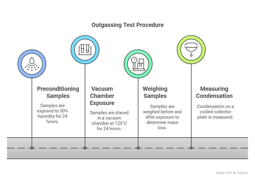
- Preconditioning samples at 50% relative humidity for 24 hours
- Placing samples in a vacuum chamber at 125°C for another 24 hours
- Weighing samples before and after exposure to determine mass loss
- Measuring condensation on a cooled collector plate
For particularly sensitive optical applications, stricter standards may apply, with requirements as low as CVCM < 0.01%. These standards prevent contamination of optical surfaces and sensitive electronic components in the vacuum of space.
Vibration and Shock Resistance in Sensor Modules
Flight-induced vibrations present substantial challenges for avionics sensors. Vibration during flight causes data deviation in sensor components, affecting navigation accuracy and system reliability. Modern sensor designs incorporate specialized vibration resistance modules to buffer these forces, thereby improving the precision of angle and acceleration sensor detection data.
Silicon-on-Insulator (SOI) pressure transducers demonstrate exceptional shock and vibration resistance across pressure ranges from 0 to 6000 psi (0-400 bar). Similarly, advanced piezoelectric accelerometers featuring ceramic materials operating in shear mode offer reduced sensitivity to base strain and transverse sensitivity below 5%.
Shock testing protocols for aerospace electronics follow rigorous standards, with test conditions ranging from 500g to 30,000g peak levels with durations between 0.12 and 1.0 milliseconds. These extreme test conditions ensure avionics can withstand not just normal operation but also unexpected mechanical stresses during flight or emergency situations.
Weight Constraints in Satellite and UAV Systems
Every gram matters in aerospace design, particularly for satellite and UAV applications. Industry standards specify maximum weight limits for avionics components, typically ranging from 20-27kg depending on specification standards. These constraints drive material selection toward options with exceptional strength-to-weight ratios.
High-performance thermoplastics offer a compelling solution to these weight challenges, providing structural integrity while significantly reducing overall mass compared to metallic alternatives. For UAV systems specifically, vibration-resistant sensor assemblies must be designed with minimal weight impact while maintaining robust performance characteristics.
The integration of advanced composite materials and high-performance thermoplastics thus represents a critical engineering approach for meeting the increasingly stringent weight requirements of modern aerospace applications.
Material Advantages of High-Performance Thermoplastics
Advanced thermoplastics offer exceptional material properties that directly address the demanding requirements of modern avionics systems. These engineered polymers deliver performance characteristics previously unattainable with conventional materials, making them increasingly indispensable in aerospace applications.
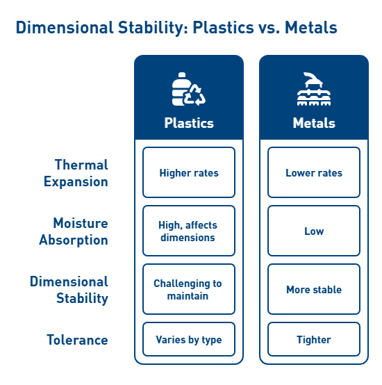
Dimensional Stability Under Thermal Stress
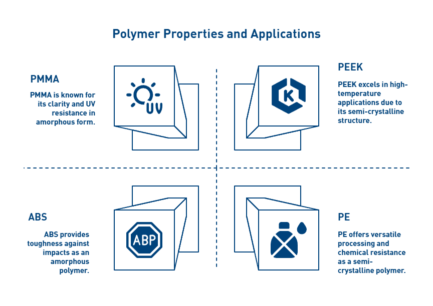
Thermoplastic composites maintain their structural integrity even when subjected to extreme thermal conditions. High-performance materials like PEEK demonstrate remarkable dimensional stability with a glass transition temperature exceeding 143°C. This thermal stability enables components to retain their precise dimensions throughout repeated thermal cycling, a critical requirement for avionics reliability.
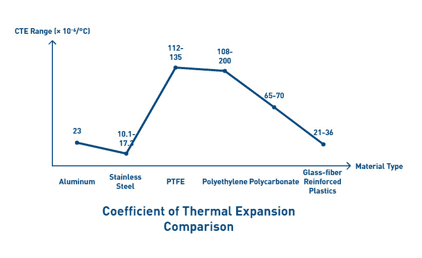
The dimensional stability of thermoplastics stems primarily from their unique molecular structure. Semi-crystalline thermoplastics such as PEEK provide superior rigidity and strength through their crystal structure, consequently reducing thermal expansion. Furthermore, carbon fiber reinforced thermoplastics can achieve thermal expansion rates comparable to metal alloys, thereby maintaining tight tolerances despite temperature fluctuations.
Testing data shows that after exposure to thermal cycling, high-performance thermoplastics exhibit minimal warpage. For instance, RYTON maintains dimensional stability even for intricate parts manufactured with tight tolerances. This property is crucial for precision-machined components in avionics systems where dimensional accuracy directly impacts performance reliability.
Electrical Insulation in High-Voltage Avionics
Modern aircraft electrical systems operate at increasingly higher voltages, necessitating superior insulation materials. ULTEM demonstrates one of the highest dielectric strengths among thermoplastic materials, making it exceptionally effective as an electrical insulator in avionics applications. Its electrical insulation properties, coupled with inherent flame resistance and low smoke generation, provide both performance and safety benefits.
Notably, PEEK offers excellent electrical insulation properties with low dielectric constant and dissipation factor. These characteristics make it ideal for avionics applications where electrical reliability and consistency are paramount. In addition, many thermoplastics can be modified to achieve static dissipative or electrically conductive qualities when required for specific applications.
Chemical Resistance to Jet Fuels and Hydraulic Fluids
Avionics materials must withstand continuous exposure to various chemicals present in aerospace environments. CELAZOLE retains 100% tensile strength after being submerged in hydraulic fluid at 200°F for thirty days, demonstrating exceptional chemical resistance. Similarly, KYNAR exhibits impressive chemical resistance at both ambient and elevated temperatures.
DuPont’s Vamac® ethylene acrylic elastomer demonstrates excellent resistance to hot oils, hydrocarbon-based lubricants, and hydraulic fluids. Moreover, materials like Kalrez® perfluoroelastomer parts resist over 1,800 different chemicals while providing temperature stability up to 327°C. These properties ensure longevity and reliability of components exposed to the aggressive chemical environment present in aircraft systems.
Independent testing reveals that PVDF stands out among thermoplastics for chemical resistance. No other thermoplastic piping material approaches PVDF’s combination of strength, chemical resistance, and operating temperature capability. Essentially, this makes it ideal for systems handling wet or dry chlorine, bromine, and other halogens.
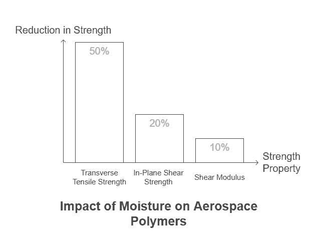
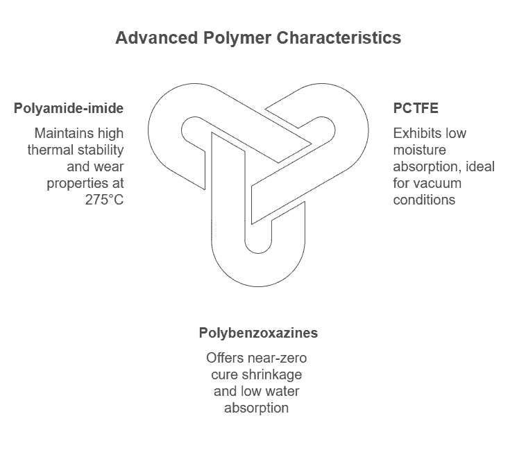
Low Moisture Absorption and Long-Term Reliability
Thermoplastics generally exhibit lower moisture absorption rates than many competing materials, directly enhancing long-term reliability in humid aerospace environments. TECHTRON demonstrates virtually zero moisture absorption, allowing products manufactured from this material to maintain extreme dimensional and density stability. In contrast, polyamides (nylons) absorb more moisture, which can affect their dimensional stability and mechanical properties.
VESTAKEEP® PEEK has proven effective as a replacement for metallic components in brackets, clips, and fasteners, primarily due to its resistance to environmental factors including moisture. VESTAMID® PA12 provides an excellent combination of mechanical properties and chemical resistance across a wide temperature range, making it suitable for components requiring long-term reliability.
The resistance to moisture absorption translates directly to improved performance in avionics applications. Thermoplastic composites generally demonstrate improved mechanical activity in humid environments, maintaining their structural integrity where other materials might degrade. This property, combined with excellent chemical resistance and thermal stability, makes high-performance thermoplastics ideal materials for avionics systems operating in diverse and challenging aerospace environments.
Key Thermoplastics Used in Avionics Systems
Material selection for avionics applications requires careful consideration of specific performance characteristics under extreme operating conditions. Several high-performance thermoplastics have emerged as frontrunners for critical avionics components, each offering unique advantages.
PEEK for Sensor Housings and Cable Insulation
PEEK (Polyetheretherketone) excels in harsh aerospace environments with its exceptional tensile strength ranging from 90 MPa to 160 MPa (13,000 to 23,000 psi). This semi-crystalline thermoplastic maintains dimensional integrity at continuous operating temperatures up to 260°C, making it ideal for sensor housings exposed to extreme thermal conditions.
PEEK’s outstanding chemical resistance shields avionics components from jet fuels, hydraulic fluids, and other aggressive substances commonly encountered in aircraft operations. Its excellent electrical insulation properties provide reliable protection for sensitive components, therefore minimizing signal interference in complex sensor networks.
For cable insulation applications, PEEK demonstrates remarkable abrasion resistance and dielectric strength. Indeed, these properties ensure signal integrity even when cables are routed through high-vibration zones near engines or control surfaces. Unlike conventional insulation materials, PEEK cables require little or no additional varnish while maintaining performance in long, continuous lengths without pinholes.
Torlon® in High-Load Connectors and Bushings
Torlon® PAI (Polyamide-imide) offers the highest tensile strength among non-filled, injection-moldable thermoplastics. With exceptional compressive strength and low creep under load, Torlon® 4203 serves as an optimal material for blocker door bushings that must maintain precise operation at temperatures ranging from -40°F to 500°F (-40°C to 260°C).
Throughout the aerospace sector, Torlon® functions effectively in applications requiring high mechanical loads. Boeing engineers utilize Torlon® 4203 for thermal isolators that prevent heat transfer between hydraulic lines and fuel tanks. Furthermore, F-16 fuel connectors made from Torlon® 4203 withstand pressures beyond 650 psi while resisting jet fuel and continuous vibration.
Vespel® for Thermal Isolation and Wear Resistance
Vespel® polyimide parts deliver continuous performance from cryogenic to high temperatures, with capability to withstand temperatures up to 260°C (500°F). This material offers an impressive combination of low wear, low friction, and outstanding creep resistance.
Since 1965, Vespel® has outperformed other engineering materials in demanding aerospace applications. It provides superior thermal isolation properties, primarily because of its low thermal expansion coefficient and outstanding insulation characteristics. These attributes make Vespel® ideal for stator vane seals, variable bushing packing, and nacelle insulation.
Ultem™ in Lightweight Structural Brackets
Ultem™ (Polyetherimide) combines exceptional strength with inherent flame retardance, featuring UL 94 V-0 rating and compliance with FAR 25.853 regulations. Its high strength-to-weight ratio makes it particularly valuable for structural brackets in weight-sensitive avionics systems.
ULTEM 9085 resin has become the material of choice for lightweight yet strong components such as cabin brackets and ducting. With a glass transition temperature of 217°C, Ultem™ maintains performance in demanding thermal environments. Subsequently, this thermoplastic serves as an effective replacement for metallic components in clips, fasteners, and structural elements throughout modern aircraft.
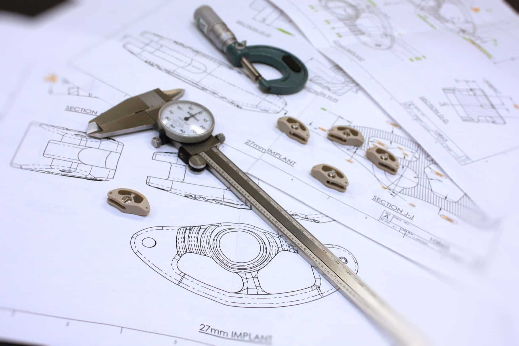
Precision Machining for Aerospace-Grade Thermoplastics
Precision machining of aerospace-grade thermoplastics requires specialized expertise to preserve material integrity. Fabricating high-performance polymer components for avionics systems demands attention to detail far beyond conventional machining practices.
Maintaining Tolerances Within ±0.002mm
Aerospace CNC machining can achieve remarkably tight tolerances down to 0.002mm, critical for components where precision directly impacts flight safety. This level of accuracy enables proper fit and function between interconnected avionics components. Simultaneously, aerospace manufacturers must manage increasingly complex geometries while maintaining these exacting standards across varied thermoplastic materials.
State-of-the-art inspection systems verify that each machined component meets specifications, as a single imperfect part could compromise aircraft performance. For avionics sensor housings, these tight tolerances ensure calibration accuracy in flight environments where millimeter deviations can affect critical navigation data.
Avoiding Delamination and Stress Cracking
Environmental stress cracking (ESC) presents a significant challenge when machining amorphous thermoplastics like Ultem®. This premature brittle failure occurs through the combination of mechanical stress and chemical contact. Among glassy polymers, approximately 40% of failures relate to ESC.
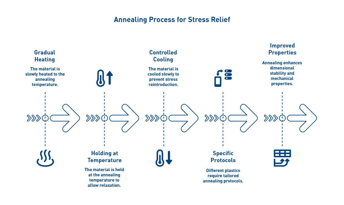
To minimize this risk, proper annealing before machining is essential. This heat treatment process relieves internal stresses that might otherwise lead to cracking during machining operations. For components requiring extensive machining time, intermediate annealing steps maintain dimensional stability.
When drilling PEEK, special attention must be paid to its lower elongation compared to other thermoplastics. Deep hole drilling into heavy cross-sections without adequate coolant can lead to cracking. Peck drilling techniques help remove swarf and prevent excessive heat buildup.
Tooling Considerations for PEEK and Ultem™
PEEK machining requires specific tooling approaches:
- Carbide tooling works for short production runs
- Polycrystalline diamond (PCD) tooling performs best for tight tolerance parts and reinforced grades
- Four-fluted end mills maximize surface finish quality
- Low helix drill bits with flood coolant optimize hole quality
For Ultem™, non-aromatic water-soluble coolants provide ideal surface finishes and maintain close tolerances. Petroleum-based coolants must be avoided as they can attack the material, potentially causing parts to develop cracks over time.
Contamination Control in Cleanroom Environments
Contamination represents a critical concern when machining polymer components for technically demanding aerospace applications. To ensure the highest level of sanitation, specialized facilities design, heat-treat, and machine plastics in controlled environments with metalwork processed separately.
For critical aerospace components, contamination control strategies must address various contaminant sources, including dust, airborne microbes, and chemical vapors. Cleanroom classification, determined by particles per cubic meter, directly impacts the precision and quality of machined components.
Compliance and Certification in Avionics Manufacturing
Regulatory compliance forms the cornerstone of avionics manufacturing, establishing rigorous frameworks that ensure component reliability in critical aerospace applications. Manufacturers must navigate complex certification landscapes to deliver qualified materials for next-generation avionics systems.
AS9100D Requirements for Aerospace Components
AS9100D builds upon ISO 9001:2015 quality management requirements by adding specifications tailored explicitly for aviation, space, and defense organizations. This standard requires organizations to:
- Implement processes for identifying and mitigating risks associated with products and supply chains
- Maintain strict configuration management for product definitions
- Establish validation procedures for special processes that cannot be fully verified
- Develop systems for handling counterfeit parts
- Incorporate human factors and product safety considerations into manufacturing processes
The standard emphasizes that requirements are complementary (not alternative) to customer and regulatory requirements, with the latter taking precedence in cases of conflict.
Traceability and Lot Control in Production
Traceability in aerospace manufacturing is not merely desirable—it is absolutely essential. Effective lot control systems enable manufacturers to track components from raw materials through final assembly, providing critical accountability throughout the production process.
For aerospace components, manufacturers must implement systems that maintain traceability records for a minimum of 10 years. Certificates of Conformance (C of C) must accompany products with comprehensive documentation including manufacturer details, certificate reference numbers, part numbers, serial numbers, and batch identifiers.
Material Validation for Outgassing and FST
Outgassing validation follows ASTM E595 standards—sometimes referred to as the NASA Low Outgassing Specification. This testing occurs at 125°C under vacuum conditions of 5 x 10^-5 Torr for 24 hours. Materials must demonstrate:
- Total Mass Loss (TML) less than 1.00%
- Collected Volatile Condensable Material (CVCM) less than 0.10%
These parameters prove particularly critical for avionics components where outgassing could potentially compromise optical surfaces or disrupt electrical continuity.
Supplier Qualification and Audit Readiness
Supplier qualification processes typically involve rigorous assessments of quality systems, production processes, and standards compliance. Regular supplier audits help identify potential risks and inefficiencies, enabling timely corrective actions.
Audit readiness requires maintaining comprehensive documentation of compliance with regulatory requirements, including traceability records, material validations, and supplier evaluations. Organizations must demonstrate systematic approaches to risk identification, prioritization, and mitigation across all processes.
Conclusion
High-performance thermoplastics have unmistakably transformed the landscape of avionics materials in aerospace applications. These advanced polymers effectively address the extreme environmental challenges faced during flight operations while delivering exceptional performance benefits. Consequently, materials like PEEK, Torlon®, Vespel®, and Ultem™ have become indispensable components in modern aircraft design, particularly as the industry continues to demand lighter, more reliable, and more efficient systems.
The shift toward these thermoplastics stems primarily from their remarkable property combinations. Unlike traditional metal components, these materials offer up to 70% weight reduction while maintaining structural integrity under thermal cycling between -55°C and +95°C. Additionally, their excellent electrical insulation characteristics protect sensitive avionics from signal interference, thus ensuring consistent performance across varying flight conditions. The chemical resistance these materials demonstrate against jet fuels and hydraulic fluids further extends component lifespan and reliability.
Though material selection represents a critical factor in avionics performance, precision machining equally determines component quality. Aerospace manufacturers must maintain tolerances within ±0.002mm while preventing delamination and stress cracking—challenges that require specialized expertise and equipment. Strict adherence to AS9100D requirements, comprehensive traceability protocols, and rigorous material validation processes therefore establish the foundation for manufacturing flight-worthy components.
The aerospace industry will undoubtedly continue exploring and developing advanced thermoplastic solutions as aircraft designs evolve toward greater efficiency and performance. Looking for precision-machined avionics materials built to perform in mission-critical environments? AIP Precision Machining delivers AS9100D-certified components crafted from high-performance thermoplastics for aerospace applications. Contact our engineering team today to discuss your application requirements or request a material consultation.
FAQs
Q1. What are the main advantages of using high-performance thermoplastics in avionics?
High-performance thermoplastics offer significant weight reduction (up to 70% lighter than steel), excellent thermal stability, superior electrical insulation, and high chemical resistance. These properties make them ideal for withstanding extreme conditions in aerospace applications while improving fuel efficiency.
Q2. How do thermoplastics like PEEK perform in extreme temperature conditions?
PEEK demonstrates exceptional thermal stability with a melting point of approximately 343°C. It can maintain its structural integrity and dimensional stability across a wide temperature range, typically from -55°C to +95°C, making it suitable for the harsh thermal cycling experienced during flight.
Q3. What are some key thermoplastics used in avionics systems?
Some key thermoplastics used in avionics include PEEK for sensor housings and cable insulation, Torlon® for high-load connectors and bushings, Vespel® for thermal isolation and wear resistance, and Ultem™ for lightweight structural brackets.
Q4. What challenges are involved in machining aerospace-grade thermoplastics?
Machining aerospace-grade thermoplastics requires maintaining extremely tight tolerances (within ±0.002mm), avoiding delamination and stress cracking, using specialized tooling for materials like PEEK and Ultem™, and ensuring contamination control in cleanroom environments.
Q5. What compliance standards are important in avionics manufacturing?
Key compliance standards in avionics manufacturing include AS9100D for aerospace components, strict traceability and lot control requirements, material validation for outgassing and FST (flame, smoke, toxicity), and supplier qualification processes. These standards ensure the reliability and safety of avionics components in critical aerospace applications.


 The relationship between structural weight and battery performance is fundamental to eVTOL viability. Battery-powered eVTOLs face a challenging physics problem—their weights remain constant throughout flight, unlike conventional aircraft that become lighter as fuel burns.